Building a GPU PC, Part 11: Mounting the Motherboard and Wiring the Case

This time, we will mount the motherboard in the case and take care of the various cable connections.
1. Fit the standoff screws
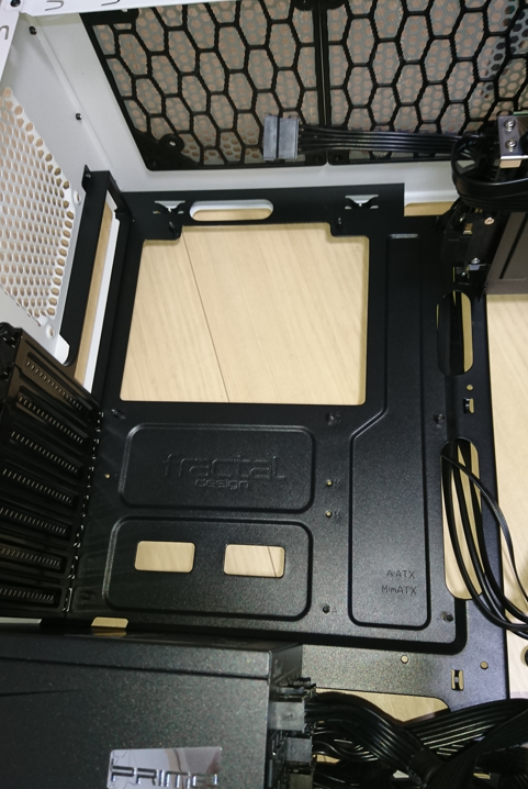
The case comes with what are called standoff screws (spacers). We will screw these into the case. The standoffs are there to hold the motherboard in place while keeping it "raised" off the case.
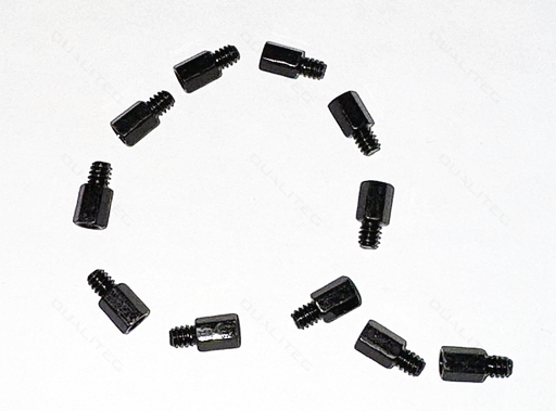
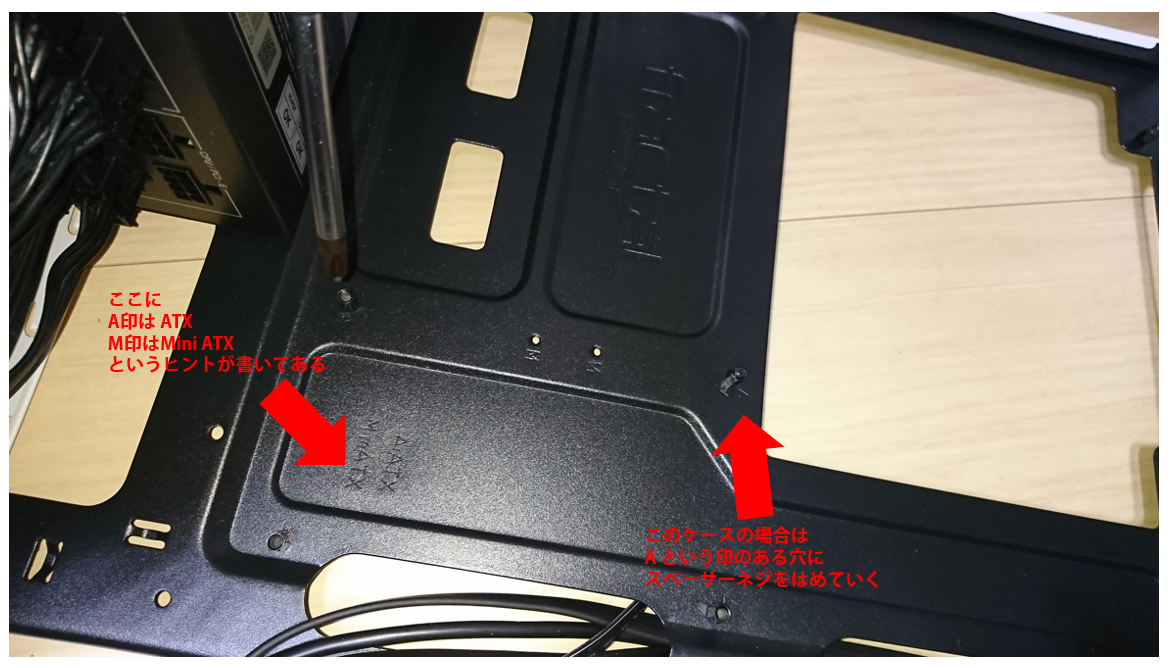
We screw these standoffs into the screw holes provided in the case. The case already has the holes pre-drilled, and there are hints printed next to them.
This case supports motherboards in the ATX and Mini ATX form factors, and each screw hole is labeled with a hint indicating which form factor it is meant for.
What is a form factor?
A form factor refers to the standard for the size and shape of a PC case, defined mainly by its compatibility with motherboards. The main form factors include the following:
- ATX:
- Standard ATX is the most common form factor, offering many expansion slots and a rich set of connection ports. Its size is roughly 30.5 cm x 24.4 cm.
- Micro-ATX is smaller than standard ATX, at about 24.4 cm x 24.4 cm. It has fewer expansion slots, but it is chosen when building a more compact PC.
- Mini-ATX is an even smaller form factor, suited to very limited spaces.
- Mini-ITX:
- At about 17 cm x 17 cm, it is designed to fit into very small PC cases. It is well suited to space-saving PCs, media centers, and small servers.
- E-ATX (Extended ATX):
- Larger than standard ATX, it is mainly used for high-performance workstations and gaming PCs. Because of its larger size, it can accommodate more expansion cards and other components.
This PC case is in the ATX form factor, but it can also take a smaller Mini ATX motherboard.
That is why it has screw holes for ATX as well as screw holes for Mini ATX.
Since our motherboard is ATX, we install the standoff screws in the ATX screw holes.
Incidentally, if you were to skip the standoffs and place the motherboard directly on the PC case, it would short out and cause serious trouble, so never forget the standoff screws.
2. Place the motherboard in the case
Once the standoffs are in, gently place the motherboard inside the case.
Adjust its position so that the screw holes on the motherboard line up with the standoffs you just installed.
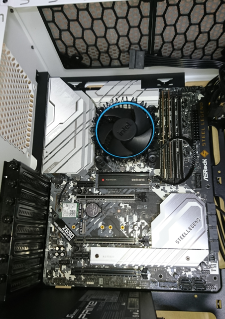
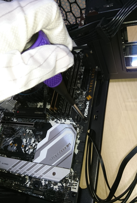
Secure the motherboard using the screws that came with the case.
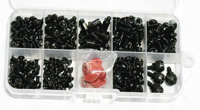
These screws roll away and get lost easily, so be careful.
Incidentally, our company has a PC assembly and repair room, and we always keep spares of parts that are easy to lose in stock. Screws are relatively inexpensive to obtain, so it may be convenient to keep some spares on hand.
3. Wiring the motherboard to the case
Peripheral components are not the only things that get wired to the motherboard.
The PC case has a power switch, USB ports, audio jacks, and so on installed in its front panel, and these need to be connected to the motherboard.
3-1 Connect the power button, reset button, and related cables
Connect the bundle of front-panel power button cables coming out of the case to the motherboard.
This area of the motherboard is where the jumper pins for connecting the front-panel power button cable bundle are located.
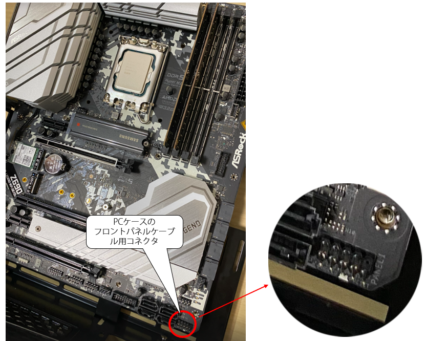
Check the pin layout in the manual.
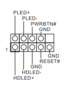
The pin assignment alone may not make much sense on its own, so I have added some supplementary notes below.
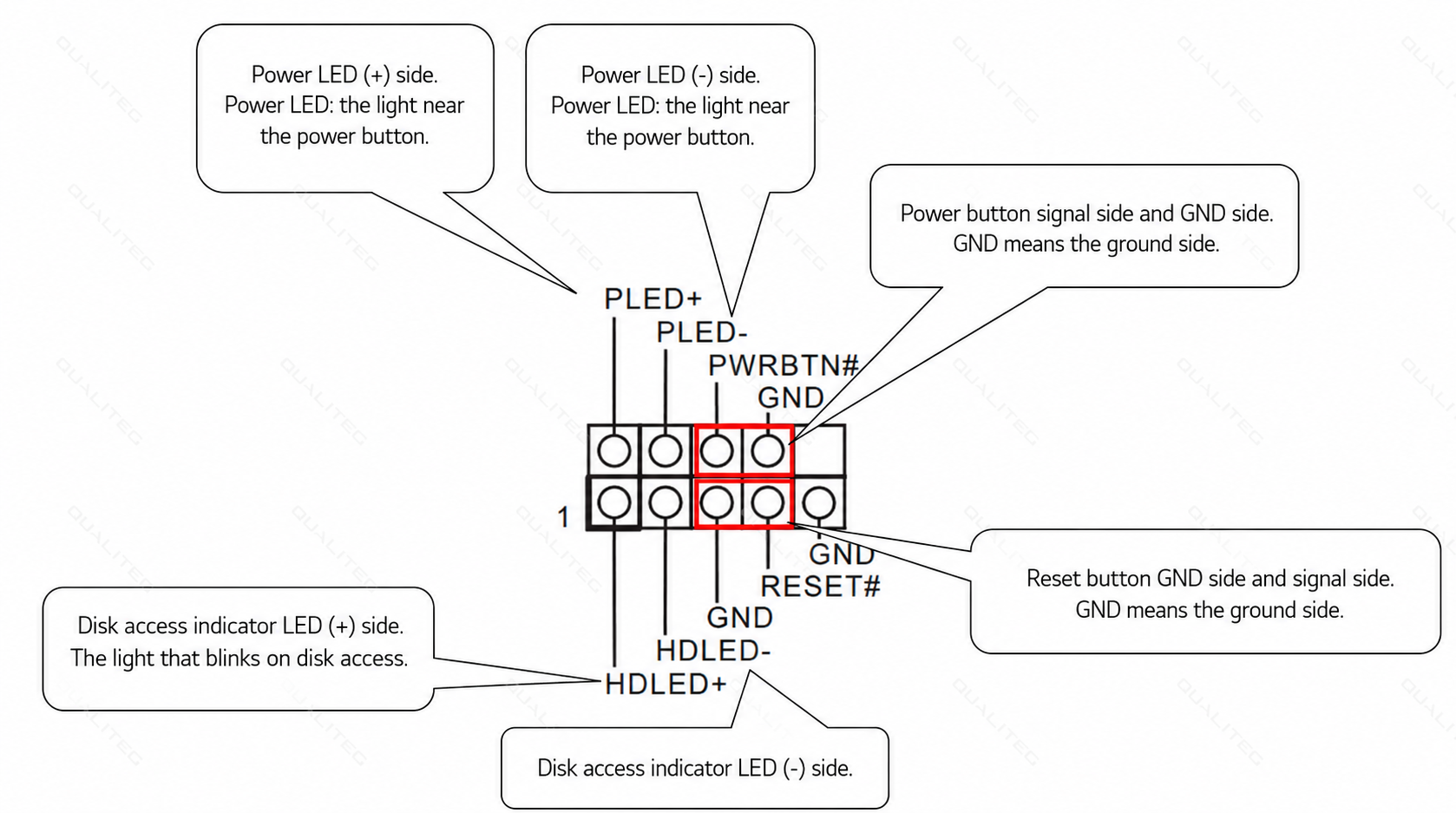
Using this as a reference, plug the PC case's power-related cables into the motherboard. This is somewhat fiddly work.
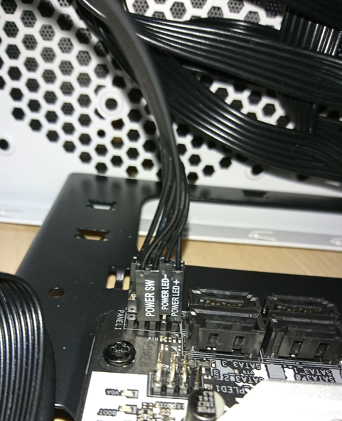
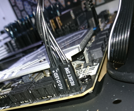
Like this, we connect the front-panel power connectors coming from the PC case to the power jumper pins on the motherboard.
It looks like the pin layout from earlier viewed from the opposite side.
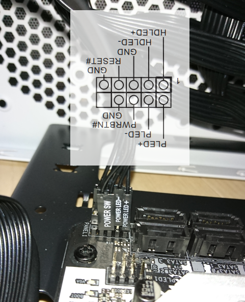
The other side is connected like this as well.
3-2 Connecting the USB 3 cable
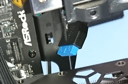
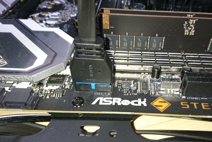
Next, connect the USB 3 cable coming out of the PC case to the motherboard.
3-3 Connecting the USB 2 cable
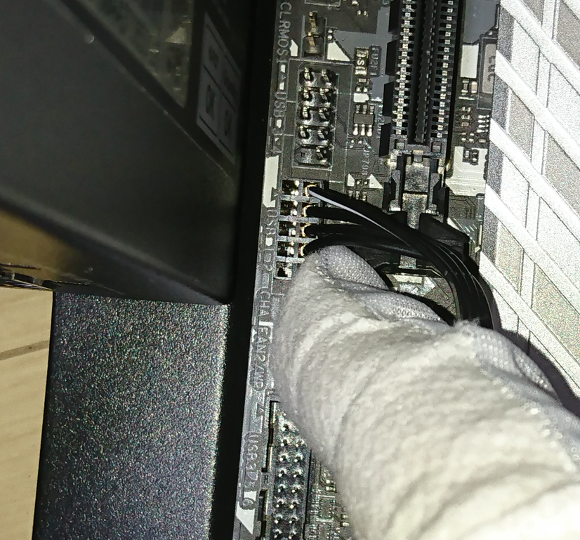
Likewise, connect the USB 2 cable coming out of the case to the motherboard.
3-4 Plug in the SATA cable
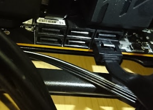
Plug the SATA cable coming from the removable SATA enclosure we installed in the 5-inch bay into a SATA connector on the motherboard. Here we used the connector labeled SATA A. The labels are usually printed on the motherboard, which is convenient.
3-5 Plug in the audio cable
Pull out the audio cable coming from the back of the case
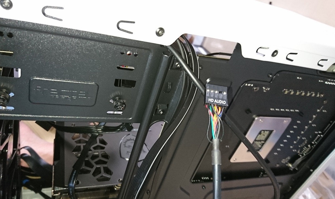
and plug it into HD AUDIO1 on the motherboard.
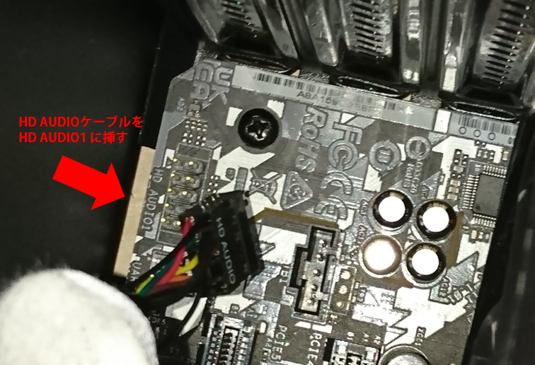
With the audio cable connected, all of the PC case's front-panel cables are now wired up.
Looking beyond DIY builds toward GPU environments for research and business?
The know-how gained from building your own GPU machine carries over directly to infrastructure choices for research, PoCs, and production.
We build and operate our own GPU cluster in-house and develop LLM products on it. We can also support a wide range of needs, from procuring GPU workstations for research to Intel Core and Intel Xeon architectures, covering everything from consumer to professional use. Beyond helping you procure and build workstations, we advise on what comes next, from setting up training environments to selecting the right GPUs, optimizing inference, and designing distributed configurations, all based on hands-on operational experience.
See our LLM infrastructure and platform technology services →In the next installment, we will install the graphics card.
navigation