
Using a Luckfox Pico M from Anywhere: Putting a Public URL on a $25, 64 MB Linux Board with WireCanal
How we made a ¥3,750 (~$25) Linux board — the Luckfox Pico M (RV1103, 64 MB, USB-C only) — reachable from the internet without adding an inbound port for web publishing: SD imaging, RNDIS networking, WireCanal's free plan, a browser-controlled LED, and 33-second reboot recovery, all measured.

Hello!
This is the Qualiteg Product Development Team!
Today we took the Luckfox Pico M — a tiny Linux board that costs less than ¥4,000 (about US$25) — and made it controllable over the internet. For the NAT traversal we used the free plan of WireCanal, our own product.
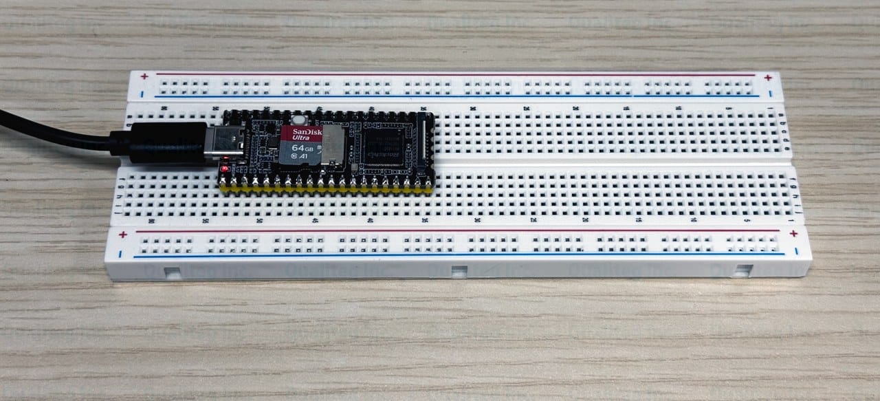
The other day we picked up a Luckfox Pico M for ¥3,750 (tax included) at Sengoku Densho, an electronics parts shop in Akihabara, Tokyo.
It is about the same size as a Raspberry Pi Pico, comes with the pin headers pre-soldered, and carries a Rockchip RV1103 (ARM Cortex-A7 at 1.2 GHz) with 64 MB of RAM, booting from a microSD card.
A board that runs Linux, at this price and this size.
We are going to make this usable from outside the house — over the internet.
The board has no RJ45 connector (no LAN port) and no Wi-Fi. All it has is a single USB-C port.
Even so, we want to make it reachable from the internet side and hit it from a phone.
So — can it be done?
To cut to the chase: it worked.
Without adding any inbound port for web publishing on the board, and with nothing more than the free plan ($0) of WireCanal, we got to the point where a web server running on the Luckfox is visible at a public URL.
On top of that, this time we wired a single LED to the board and made it switchable — on and off — across the internet, with buttons on the public page.
Reboot the board, and the public URL comes back on its own in a measured 33 seconds.
One caveat: the Pico M itself has neither Wi-Fi nor RJ45, so we use a USB-connected Windows PC as its gateway to the internet.
(We plan to post experiments with Ethernet-equipped LuckFox boards in the future!)
So for this build, the PC needs to be running when you access the board from outside.
This article walks through everything we actually did, with measured numbers from start to finish: writing the image to the SD card, booting, networking, wiring the LED, publishing through WireCanal, and setting up a persistent service that survives reboots.
The subject is the Luckfox Pico M (the plain Luckfox Pico with pin headers pre-installed) and the official Buildroot image, with a Windows 11 machine as the work PC. WireCanal is a service we develop and operate ourselves, and the figures in this article are actual measurements as of August 19, 2026.
What kind of board is the Luckfox Pico M?
Luckfox is a series of small Linux boards built around Rockchip's vision-oriented SoCs (RV1103 / RV1106), and the Pico M is the entry model. Here is what we confirmed on our actual unit.
| Item | Value confirmed on the actual board |
|---|---|
| SoC | Rockchip RV1103 (ARM Cortex-A7 1.2 GHz, 32-bit, NEON/VFPv4) + RISC-V MCU + 0.5 TOPS NPU |
| Memory | 64 MB DDR2. Linux sees 33 MB (the rest is reserved for the NPU/ISP and other subsystems) |
| OS | Buildroot (official image, 250607 build, Linux 5.10.160, busybox init, python3 3.11 included) |
| Storage | Boots from a microSD (TF) card. Root filesystem is a 6 GB ext4 |
| Connectivity | USB-C (power + RNDIS virtual NIC + ADB). Ethernet is pads only (no RJ45) |
| Price | ¥3,750 (tax included, Sengoku Densho, August 2026) |
Unlike a Raspberry Pi, neither wired LAN nor Wi-Fi works "out of the box".
So this time, we use the trick of connecting the board to a PC over USB-C, which brings up a virtual network adapter (RNDIS) and forms a tiny network that exists only between the PC and the board.
You could also wire up a transformer-equipped RJ45 jack — a so-called MagJack — yourself and connect a LAN cable directly, but that takes a bit of work.
There are also LuckFox models that come with an RJ45 jack in the first place, so if you want a direct wired-LAN connection you can go with one of those (we plan to cover that in a separate article).
For this experiment, then, we take the route of borrowing the PC's internet connection — which means getting out to the internet takes one extra trick on the PC side (Step 3).
The other defining trait is how little memory there is.
Linux sees 33 MB.
Whether WireCanal's resident agent can run in that space and still be practical is one of the highlights of this build.
What you need
| Item | Notes |
|---|---|
| Luckfox Pico M | Bought at Sengoku Densho. We used it plugged into a breadboard |
| microSD card | A few GB is plenty. We used a 64 GB card we had on hand |
| USB-C cable | Must support data (charge-only cables will not expose RNDIS) |
| LED and a resistor (1 kΩ; a few hundred Ω to 1 kΩ works) | For the browser-controlled demo. On the breadboard, wire "physical pin 4 → resistor → LED → physical pin 3 (GND)" (explained in the wiring section) |
| Windows PC | Windows 11 Pro (with the Hyper-V virtualization platform enabled). Used for writing the SD card and for internet sharing. We also use pscp.exe from PuTTY to transfer files to the board |
| A WireCanal account | The free plan ($0, no credit card required) covers everything in this article |
WireCanal's free plan gives you one canal (a pair of a public URL and a forward target), with a randomly assigned subdomain as the public address.
A canal you create stays alive as long as the Agent keeps using it, and expires 72 hours after the Agent's last connection. If you keep it running as a resident service, as we do here, the URL is preserved.
Step 1: Write the Buildroot image to the microSD card
First, gather the files and tools. Everything comes from official sources, and the Flash Image page on the Luckfox Wiki links to all of them. You download three things.
| Download | Where to get it |
|---|---|
| OS image | Open the "Official Buildroot" link on the Flash Image page — it opens a Google Drive folder. Inside its "MicroSD" folder are five model-specific zips; pick Luckfox_Pico_MicroSD_250607.zip (for the plain Luckfox Pico / Pico M, about 104 MB). Be careful not to grab the Plus, Mini, ProMax, or WebBee variants |
| SocToolKit | Via "Click here to download" in the SocToolKit section of the same page (we used v1.98). This is the Windows SD-writing tool |
| SD Card Formatter | From the SD Association's official site. Used to pre-format the card |
Unpacking the OS image zip yields the following files.
env.img  idblock.img  uboot.img  boot.img  oem.img  userdata.img  rootfs.img
update.img  download.bin  sd_update.txt  tftp_update.txt
Start by formatting the card with SD Card Formatter. Install it and launch it; your card's drive appears in the card selection box. Double-check that it really is the SD card (capacity and drive letter), then press "Format" with quick format left selected. If you have other USB drives plugged in, this selection is the one thing to be careful about. In our case the card came out formatted as exFAT — SocToolKit writes the image over it in the next step, so just proceed.
Next, SocToolKit. Unpack the zip and launch SocToolKit.exe via right-click → "Run as administrator" (the official instructions note that without administrator rights it may fail to recognize the SD card). A Chip Selection dialog appears first: choose RV1103 and press OK.
The official instructions say to select RV1106, but we selected RV1103 to match the actual SoC on the board. With that selection, we confirmed everything from the completed write ("Create sdcard OK") all the way to the Pico M actually booting.
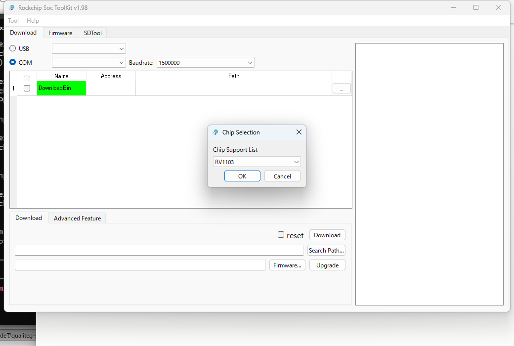
Switch to the "SDTool" tab. The Usb Disk field shows the inserted card (59.5G in our case). For the mode, select "SD Boot".
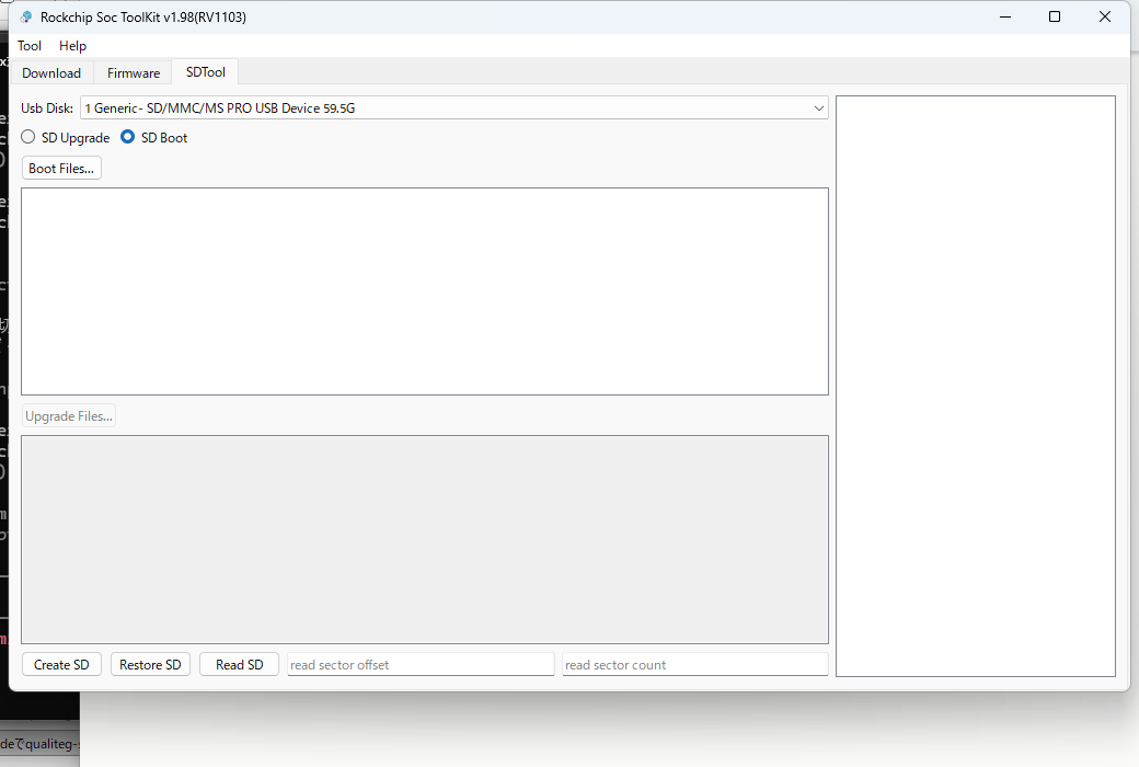
Press "Boot Files..." and a file selection dialog opens. From the folder you just unpacked, select the seven .img files together (env.img, idblock.img, uboot.img, boot.img, oem.img, userdata.img, rootfs.img). Do not include update.img. Once loaded, the seven files appear in the list.
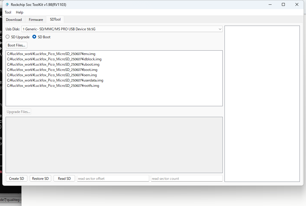
Press "Create SD" and a final confirmation dialog shows the target device. Check the device name and capacity one more time, then press Yes. The write begins, and the log on the right fills with "Write disk from file (100%)...OK" for each image. In our case it reached "Create sdcard OK" in one to two minutes. That completes the write.
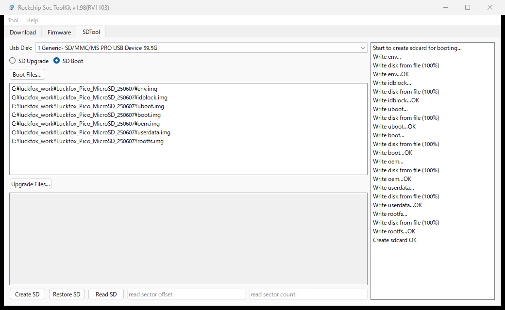
The interesting part here is that the bundled sd_update.txt spells out the layout on the SD card, sector by sector. An excerpt:
#env.img 0x0:0x0 0x40:0x8000 0x40:0x8000
#idblock.img 0x40:0x8000 0x400:0x80000 0x170:0x2E000
#uboot.img 0x440:0x88000 0x400:0x80000 0x200:0x40000
#boot.img 0x840:0x108000 0x10000:0x2000000 0x1899:0x313200
#oem.img 0x10840:0x2108000 0x100000:0x20000000 0x17C78:0x2F8F000
#userdata.img 0x110840:0x22108000 0x80000:0x10000000 0x4C4A:0x989400
#rootfs.img 0x190840:0x32108000 0xC00000:0x180000000 0x4CD80:0x99B0000
Each line reads "name, start sector:start byte, region size, actual size". In other words, what SocToolKit does is place each image verbatim at these offsets defined on the Rockchip/Luckfox side.
There is no need to create an MBR/GPT partition table yourself. The Rockchip boot ROM comes looking for idblock.img at sector 64 of the SD card (byte offset 0x8000), and boot proceeds from there (the boot-time partition layout is also held in the U-Boot environment).
If you want to write from a Linux machine, you can produce the same result by writing each image directly to the offsets in this table.
In fact, I tried exactly that myself with a bit of Python, writing each image by hand — and the board booted just fine. (That script is in the repository too, as sdwrite.py. It defaults to a dry run and writes only when given --write.)
But if you go that route, getting the target disk wrong wipes a different drive — so be careful with that one thing.
Step 2: Boot the board and log in over SSH
Insert the freshly written microSD into the Pico M and connect it to the PC over USB-C. That powers the board and it boots straight away. After about 10 seconds, a network adapter named "Remote NDIS based Internet Sharing Device" appeared on the Windows side. No extra drivers were needed (Windows 11's built-in RNDIS driver recognized it).
The board's IP address is fixed at 172.32.0.93. Incidentally, Luckfox's default 172.32.0.0/16 is outside the RFC 1918 private ranges (172.16.0.0–172.31.255.255), so watch out for conflicts if your environment has routes into that range.
Assign the PC's RNDIS adapter an address on the same network by hand. In an elevated PowerShell, check the adapter's ifIndex first, then configure it.
# Find the RNDIS adapter's ifIndex (the row whose InterfaceDescription matches Remote NDIS ...)
Get-NetAdapter | Where-Object InterfaceDescription -match 'NDIS'

# Assign a static IP to that ifIndex (example: ifIndex 41). Remove the auto-assigned 169.254.x.x first
Remove-NetIPAddress -InterfaceIndex 41 -AddressFamily IPv4 -Confirm:$false -ErrorAction SilentlyContinue
New-NetIPAddress -InterfaceIndex 41 -IPAddress 172.32.0.100 -PrefixLength 16
Now ping 172.32.0.93 gets a reply, and you can SSH in. The user is root and the initial password is luckfox.
$ ssh root@172.32.0.93
# uname -a
Linux luckfox 5.10.160 #22 Wed Jun 11 18:43:57 CST 2025 armv7l GNU/Linux
# free -m
              total        used        free      shared  buff/cache   available
Mem:             33          10           4           0          19          20
# df -h | head -2
Filesystem                Size      Used Available Use% Mounted on
/dev/root                 5.8G     79.1M      5.6G   1% /
Total memory: 33 MB. This is where we will now install the publishing machinery.
Step 3: Get the board onto the internet (via the PC)
This is the extra step that a Raspberry Pi never needed. (And, admittedly, not the most essential part of the project...)
The Pico M is connected only to the PC, so we make the PC act as a router and push the board's packets out to the world. Windows has a mechanism called WinNAT, which you can set up from an elevated PowerShell. First, check whether a NAT already exists.
# Check for an existing NAT (if anything shows up, be careful — see the note below)
Get-NetNat
Using WinNAT assumes, per Microsoft's official procedure, that Hyper-V is enabled (the PC in this article runs Windows 11 Pro with the Hyper-V virtualization platform — the same one WSL 2 uses — enabled, and that is the configuration we measured on).
Also, WinNAT supports only one internal NAT subnet prefix per PC. On machines where Docker, Hyper-V virtual networks, or similar have already created a NAT, the next command may fail. In that case the existing NAT belongs to another component — do not delete it; assess the impact on your setup before proceeding.
Once that checks out, create the NAT and enable forwarding.
New-NetNat -Name LuckfoxNAT -InternalIPInterfaceAddressPrefix 172.32.0.0/16
Set-NetIPInterface -InterfaceIndex 41 -Forwarding Enabled
On the board side, tell it the default gateway (the PC's address) and DNS.
ip route add default via 172.32.0.100 dev usb0
printf 'nameserver 1.1.1.1\nnameserver 8.8.8.8\n' > /etc/resolv.conf
Now ping 1.1.1.1 works and names resolve. HTTPS, however, still fails. Here are the two snags we hit.
The first: the image ships without a root certificate bundle (CA bundle). With no way to verify TLS peers, both Python and the agent fail with certificate verify failed. We simply copied over the Mozilla bundle that ships with Git for Windows.
# On the board: create the target directory
mkdir -p /etc/ssl/certs

# On Windows (PowerShell): copy from the PC to the board (pscp from PuTTY)
pscp -pw luckfox "C:\Program Files\Git\mingw64\etc\ssl\certs\ca-bundle.crt" root@172.32.0.93:/etc/ssl/certs/ca-certificates.crt

# On the board: fix permissions and link the path Python checks by default
chmod 644 /etc/ssl/certs/ca-certificates.crt
ln -sf /etc/ssl/certs/ca-certificates.crt /etc/ssl/cert.pem
The second: the clock. Right after boot, the board's time starts at January 1, 1970 — outside any certificate's validity window, so TLS fails for that reason too. ntpd is present, but it starts before the route exists, so we set the time by hand for now.
# Replace with the current date and time (UTC) before running
date -s '2026-08-18 08:45:51'
With those two in place, HTTPS from the board started working.
# python3 -c 'import urllib.request;print(urllib.request.urlopen("https://download.wirecanal.com/latest/VERSION").read())'
b'0.18.3\n'
The route, DNS, and clock are all lost on reboot, so we will fold them into the startup script in Step 6.
Wiring: connect one LED
Before publishing anything, let's wire up the star of this demo: the LED. We use physical pin 4 (GPIO1_C7) and its neighbor, physical pin 3 (GND).
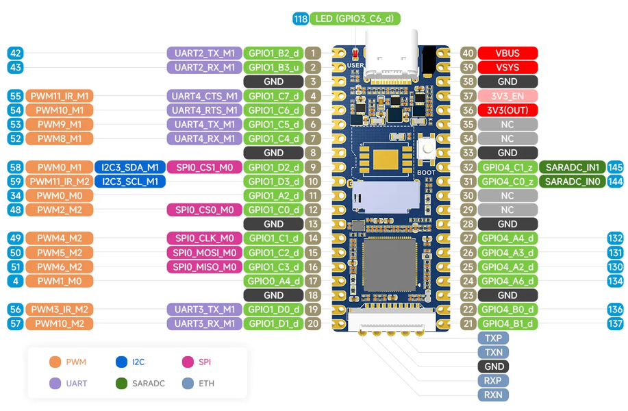
The pinout diagram is in the official GPIO documentation.
Looking at the board with the USB-C connector at the top, the third pin down the left column is GND and the fourth is GPIO1_C7.
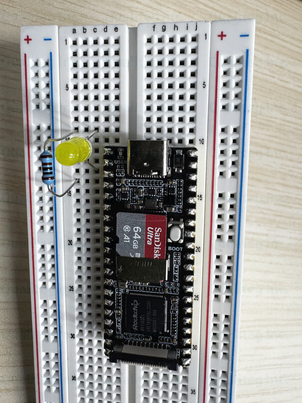
On the breadboard, we wired it up as
pin 4 → resistor (1 kΩ) → LED anode (long leg) → LED cathode (short leg) → pin 3 (GND).
The output and GND are adjacent pins, so the wiring is as short as it gets.
Note that physical pins 1 and 2 are assigned to the debug serial console (UART2), so we leave them alone for LED duty.
Once wired, check from SSH that it lights before going any further. Linux GPIO can be driven straight from sysfs.
echo 55 > /sys/class/gpio/export
echo out > /sys/class/gpio/gpio55/direction
echo 1 > /sys/class/gpio/gpio55/value   # LED on
echo 0 > /sys/class/gpio/gpio55/value   # LED off
The number 55 comes from the formula "GPIO number = bank×32 + (group as A=0…D=3)×8 + index".
For GPIO1_C7 that is 1×32 + 2×8 + 7 = 55. If echo 1 lights the LED on your breadboard, the wiring is correct.
Step 4: Create a canal in WireCanal
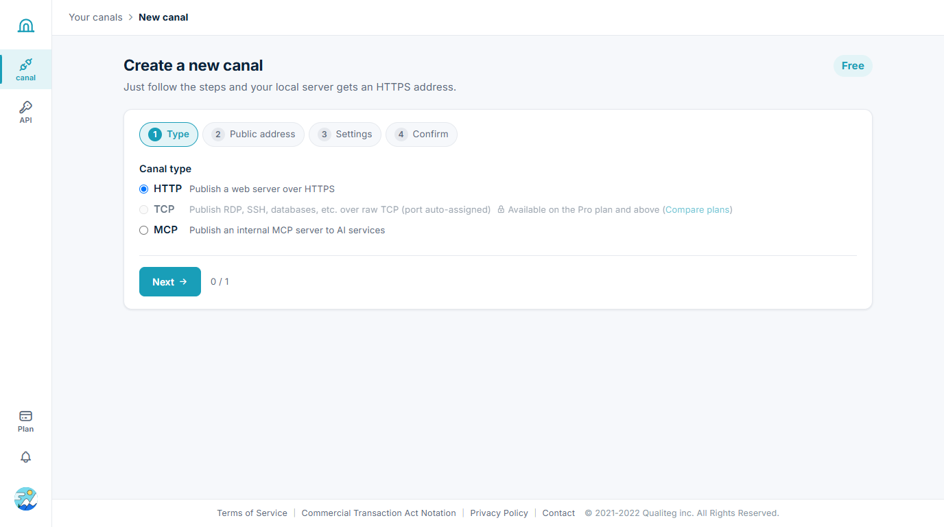
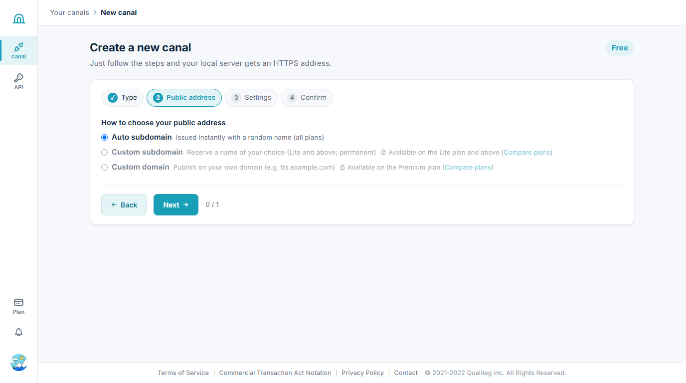
From here on, the flow is the same as in our Raspberry Pi 5 article. From the dashboard, click "Create a new canal" and go through the four-step wizard. We kept the account on the free plan and proceeded under exactly those conditions.
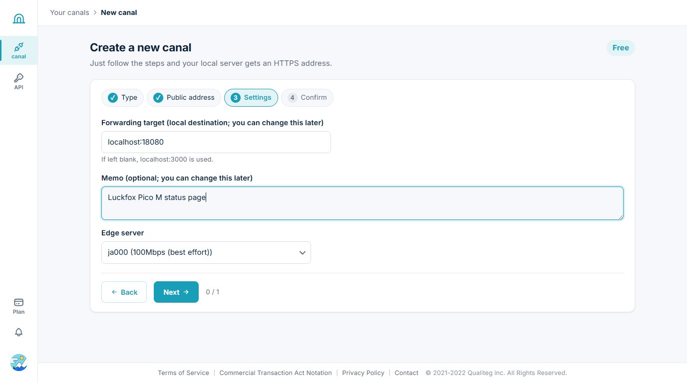
For the forward target, enter localhost:18080 — the port of the web server we are about to run inside the Luckfox.
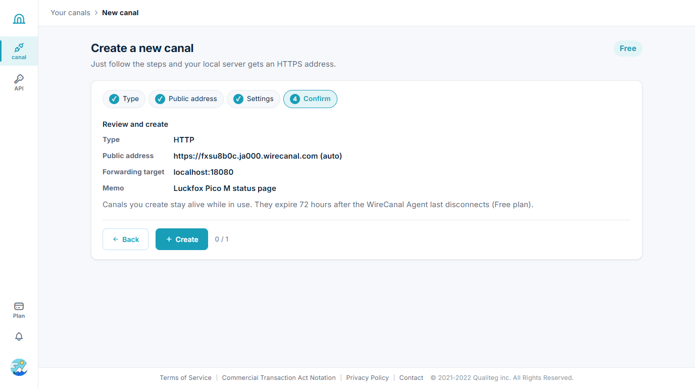
Once created, the canal detail page shows the connection file (wirecanal.json) and setup instructions. The Linux tab boils down to three steps: install the Agent with a one-liner, place wirecanal.json next to it, and start it.
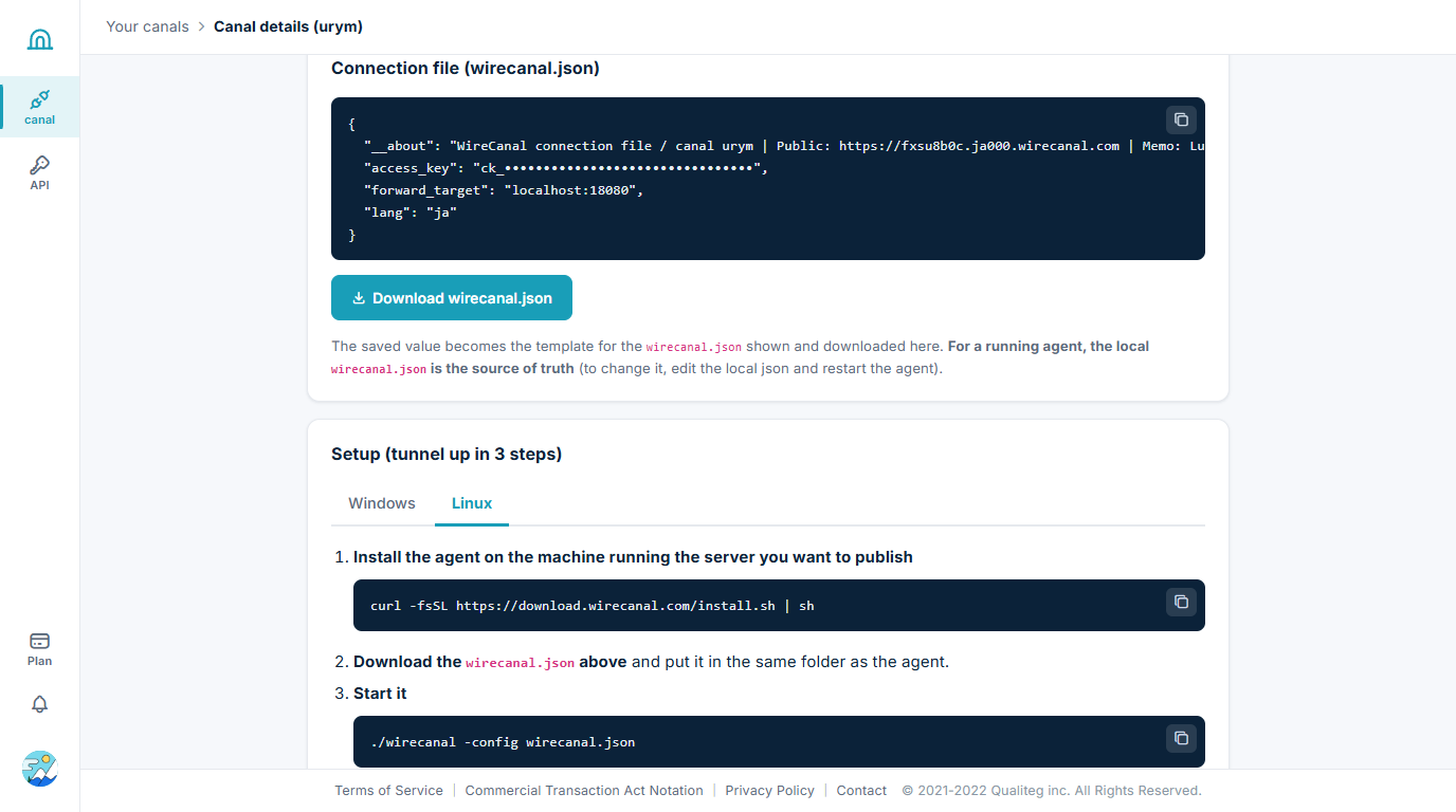
Step 5: Install the Agent on the Luckfox and publish
The WireCanal Agent is a single static binary per CPU type. The Luckfox Pico M is 32-bit ARM (uname -m reports armv7l), so we use wirecanal-linux-arm. The one-liner install.sh would auto-detect this via uname -m and fetch the same file — but this Buildroot image does not include curl. So we downloaded it on the PC and copied it to the board.
# On Windows (PowerShell)
curl.exe -fsSL https://download.wirecanal.com/latest/wirecanal-linux-arm -o wirecanal
pscp -pw luckfox wirecanal root@172.32.0.93:/root/wirecanal_demo/wirecanal
pscp -pw luckfox wirecanal.json root@172.32.0.93:/root/wirecanal_demo/wirecanal.json   # the connection file downloaded from the canal detail page
On the board, make it executable and check the version.
# cd /root/wirecanal_demo && chmod +x wirecanal && chmod 600 wirecanal.json
# ./wirecanal --version
wirecanal v.0.18.3 powered by Qualiteg Inc. https://qualiteg.com
For the content to publish, we wrote a small web server that lets you switch the LED from a browser. Press ON and the LED we just wired actually lights; press OFF and it goes dark. The button for the current state is highlighted, so you can tell at a glance which state it is in. The image includes python3, so it is written with the standard library only. It listens on 127.0.0.1 port 18080; GET /led returns the current state, and POST /led/on / /led/off switch it. Driving the LED is the same write to /sys/class/gpio we tried in the wiring section.
The complete code set (demo_server.py, S99wirecanal, settime.py, plus the supplementary sdwrite.py) is on GitHub: qualiteg/luckfox-pico-wirecanal-demo (the commit as of this article). Clone it and it works as is.
demo_server.py (as deployed on the board, in full)
# LED control page for the Luckfox Pico M
# Served on 127.0.0.1:18080 and published to the internet through a WireCanal tunnel.
# The ON/OFF buttons drive GPIO1_C7 (sysfs number 55, physical pin 4) where an LED is wired.
import http.server, subprocess, socket, html, os
GPIO = "55"
GPIO_DIR = "/sys/class/gpio/gpio" + GPIO
def gpio_init():
if not os.path.isdir(GPIO_DIR):
with open("/sys/class/gpio/export", "w") as f:
f.write(GPIO)
with open(GPIO_DIR + "/direction", "w") as f:
f.write("out")
def gpio_set(v):
with open(GPIO_DIR + "/value", "w") as f:
f.write("1" if v else "0")
def gpio_get():
with open(GPIO_DIR + "/value") as f:
return f.read().strip() == "1"
def sh(c):
try: return subprocess.run(c, shell=True, capture_output=True, text=True, timeout=5).stdout.strip()
except Exception as e: return str(e)
PAGE = """<!doctype html><html lang="en"><head><meta charset="utf-8"><meta name="viewport" content="width=device-width,initial-scale=1">
<title>Luckfox Pico M LED control</title>
<style>body{font-family:system-ui,-apple-system,Segoe UI,Roboto,sans-serif;margin:0;background:#f7fafd;color:#15222b}
.wrap{max-width:720px;margin:40px auto;padding:0 20px}.card{background:#fff;border:1px solid #dde5ee;border-radius:16px;padding:28px 32px;box-shadow:0 2px 12px rgba(0,0,0,.05)}
h1{font-size:1.5rem;margin:0 0 6px}.sub{color:#5f6b78;margin:0 0 20px}table{border-collapse:collapse;width:100%%}td{padding:8px 6px;border-bottom:1px solid #eef2f6;vertical-align:top}
td:first-child{color:#5f6b78;width:150px}code{background:#f1f5f9;padding:2px 6px;border-radius:6px}
.led{display:flex;align-items:center;gap:16px;margin:18px 0 22px}
.dot{width:26px;height:26px;border-radius:50%%;background:#cfd8e3;transition:all .15s}
.dot.on{background:#e5484d;box-shadow:0 0 14px 3px rgba(229,72,77,.55)}
button{font-size:1rem;font-weight:600;border-radius:10px;border:1px solid #cdd7e1;background:#fff;color:#15222b;padding:10px 26px;cursor:pointer;transition:all .15s}
button.active{background:#1f7ae0;border-color:#1f7ae0;color:#fff}
#btnOn.active{background:#e5484d;border-color:#e5484d}
.state{font-weight:700;min-width:44px}
.foot{color:#8b96a4;font-size:.85rem;margin-top:16px}</style></head><body><div class="wrap"><div class="card">
<h1>Luckfox Pico M — LED control</h1>
<p class="sub">The buttons below drive a real LED wired to GPIO1_C7 (physical pin 4) on the board, through a WireCanal tunnel. No inbound port is exposed directly to the internet.</p>
<div class="led"><div id="dot" class="dot"></div><span id="state" class="state">...</span>
<button id="btnOn" onclick="setLed(1)">ON</button><button id="btnOff" onclick="setLed(0)">OFF</button></div>
<table>
<tr><td>Board</td><td>Luckfox Pico M (Rockchip RV1103, ARM Cortex-A7, 64 MB DDR2)</td></tr>
<tr><td>Hostname</td><td><code>%(host)s</code></td></tr>
<tr><td>Kernel</td><td><code>%(uname)s</code></td></tr>
<tr><td>Uptime</td><td>%(uptime)s</td></tr>
<tr><td>LED pin</td><td><code>GPIO1_C7</code> = sysfs gpio%(gpio)s, physical pin 4 (GND on pin 3)</td></tr>
</table>
<p class="foot">Agent: WireCanal (linux/arm) · Powered by Qualiteg</p>
</div></div>
<script>
async function refresh(){const r=await fetch('/led');const j=await r.json();
document.getElementById('dot').className='dot'+(j.on?' on':'');
document.getElementById('state').textContent=j.on?'ON':'OFF';
document.getElementById('btnOn').className=j.on?'active':'';
document.getElementById('btnOff').className=j.on?'':'active';}
async function setLed(v){await fetch('/led/'+(v?'on':'off'),{method:'POST'});refresh();}
refresh();setInterval(refresh,3000);
</script></body></html>"""
class H(http.server.BaseHTTPRequestHandler):
def _send(self, code, body, ctype="text/html; charset=utf-8"):
data = body.encode("utf-8")
self.send_response(code)
self.send_header("Content-Type", ctype)
self.send_header("Content-Length", str(len(data)))
self.end_headers()
self.wfile.write(data)
def do_GET(self):
if self.path == "/led":
return self._send(200, '{"on": %s}' % ("true" if gpio_get() else "false"), "application/json")
body = PAGE % {
"host": html.escape(socket.gethostname()),
"uname": html.escape(sh("uname -srm")),
"uptime": html.escape(sh("uptime")),
"gpio": GPIO,
}
self._send(200, body)
def do_POST(self):
if self.path == "/led/on":
gpio_set(True)
elif self.path == "/led/off":
gpio_set(False)
else:
return self._send(404, '{"error":"not found"}', "application/json")
self._send(200, '{"on": %s}' % ("true" if gpio_get() else "false"), "application/json")
def log_message(self, *a): pass
gpio_init()
http.server.HTTPServer(("127.0.0.1", 18080), H).serve_forever()One caution here. In this Buildroot environment, starting python3 -m http.server as-is crashed with Address family not supported while trying to open an IPv6 socket (this image's kernel has no IPv6). Binding explicitly to 127.0.0.1, as in the code above, avoids the problem.
Start the web server in the background, then start the Agent.
cd /root/wirecanal_demo
(setsid nohup python3 demo_server.py >/dev/null 2>&1 &)
./wirecanal -config wirecanal.json
wirecanal v.0.18.3 powered by Qualiteg Inc. https://qualiteg.com
wirecanal: warning: mode=http with no http rules configured; all paths will be forwarded to the target. To restrict to specific paths/methods, set http.default: deny plus http.rules
wirecanal: automatic updates are enabled (disable with "auto_update": false in wirecanal.json)
wirecanal: canal urym: delivering access to https://fxsu8b0c.ja000.wirecanal.com to the local forward target localhost:18080
wirecanal: review your settings at https://app.wirecanal.com/canals/urym
wirecanal 0.18.3: connecting tenant=urym mode=http forward_target=localhost:18080At this point, the connection status on the dashboard flips to "● Connected".
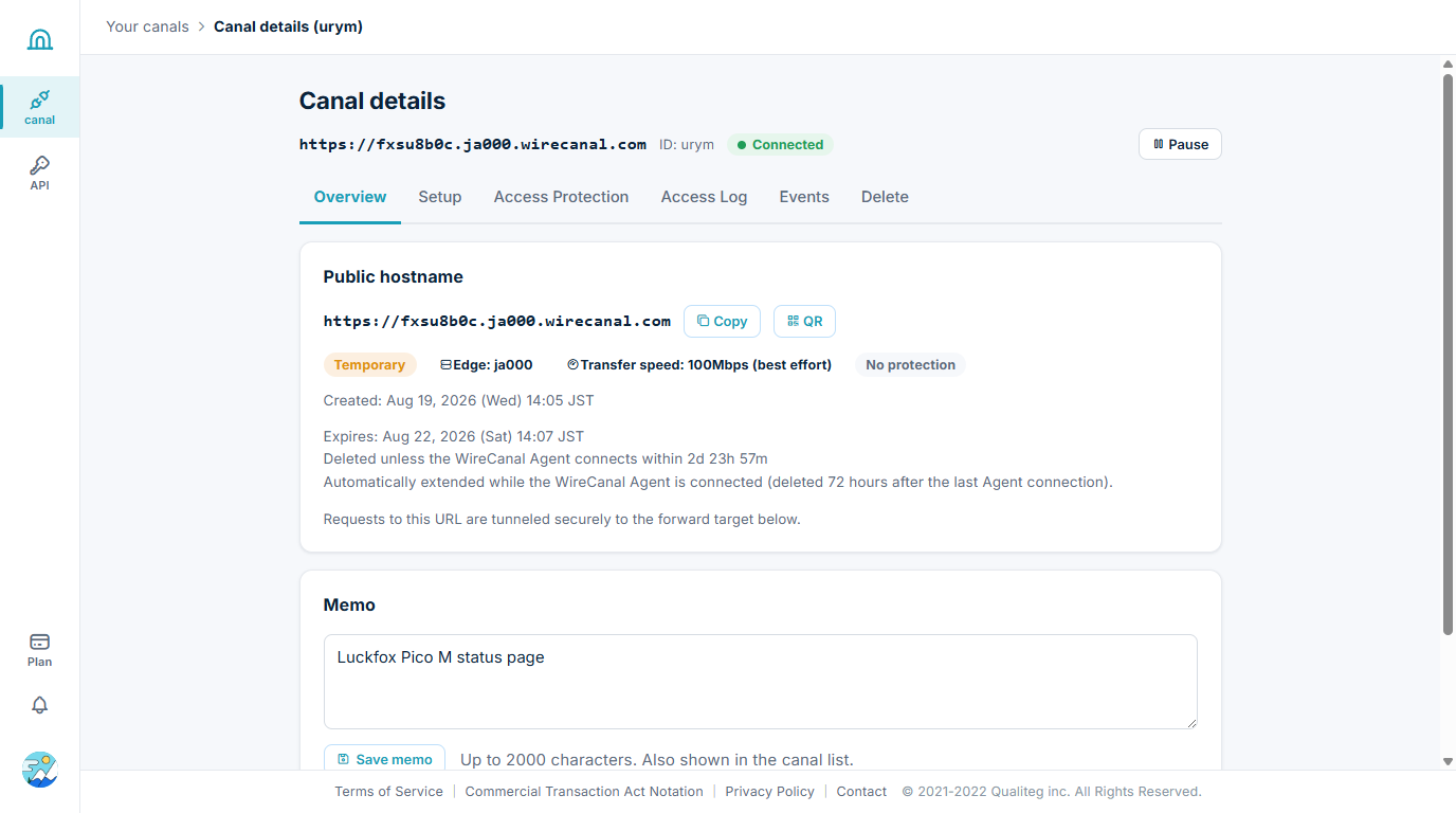
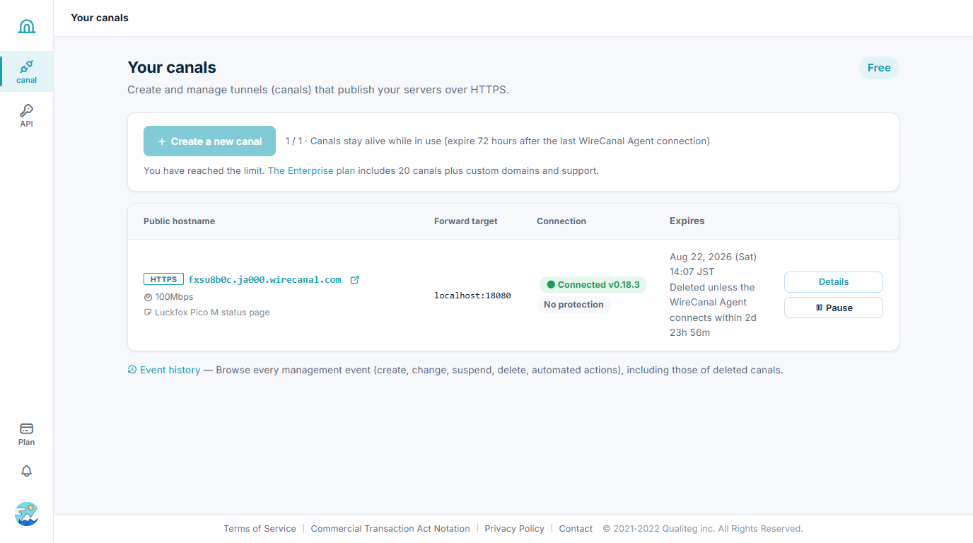
Looking at it from the internet side
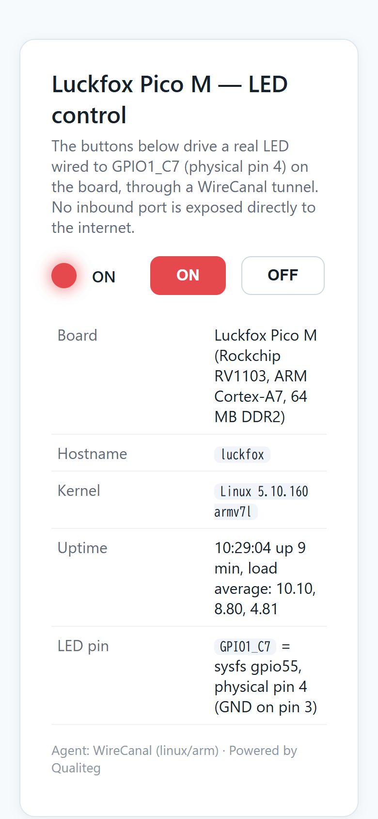
Open the public URL in a browser.
Opening the public URL and pressing ON. At this moment, the LED on our breadboard is actually lit
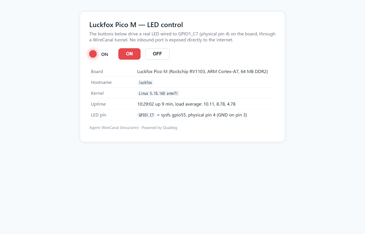
The kernel string "Linux 5.10.160 armv7l" and the uptime are the live values of the actual board we just saw over SSH, straight across the internet. And when you press the ON button, the LED actually lights up on the breadboard in front of you. The browser is just hitting a public URL — and a physical thing moves at the other end. The same URL opens on a phone, too.
Measured with curl. You can also skip the page and drive the LED through the API directly:
$ curl -s -o /dev/null -w "HTTP %{http_code} / %{time_total}s" https://fxsu8b0c.ja000.wirecanal.com/
HTTP 200 / 0.232s
$ curl -s -X POST https://fxsu8b0c.ja000.wirecanal.com/led/on
{"on": true}
$ curl -s -X POST https://fxsu8b0c.ja000.wirecanal.com/led/off
{"on": false}
At this point, there is not a single inbound port on the Pico M reachable directly from the internet. Port 18080 listens only on 127.0.0.1, and the PC's NAT has no inbound (port-forwarding) rules whatsoever. Publication rests entirely on the Agent's outbound connection. SSH (port 22) does listen on the RNDIS side, but that is the closed network between the PC and the board — unreachable from the internet.
Note that we have not added authentication, so anyone who knows the URL can view the page and operate the LED. Ours is a demo with a single resistor-protected LED, so we left it as is — but if you publish GPIO that affects real equipment (relays, motors, locks, power control), be sure to restrict who can operate it, on which paths and methods, using the canal's access protection (IP restrictions, authentication) and HTTP rules.
Step 6: Make it resident, so it comes back after a power cycle
The Step 5 processes die when you close the terminal, and the route, DNS, and clock are lost on reboot. On Raspberry Pi OS this would be a matter of dropping in a systemd unit, but Buildroot's init is busybox's /etc/init.d/S??name scheme, so we write one startup script.
Before that, we set up swap. Linux sees 33 MB of memory, and the Agent runs as a pair with a resident watchdog for automatic updates (wirecanal-safeguard), so we wanted some headroom. We carved out a 128 MB file on the SD card and enabled it.
dd if=/dev/zero of=/swapfile bs=1M count=128
chmod 600 /swapfile && mkswap /swapfile && swapon /swapfile
Here is the startup script. In order, it: enables swap, waits for the USB-side network (usb0) to get an address, installs the route and DNS, restarts ntp and waits for the clock to sync, then starts the web server and the agent. The agent runs inside a loop that relaunches it 5 seconds after it exits — our stand-in for systemd's Restart=always. The supervisor loop's PID is recorded in a file, which both prevents double starts and lets stop take down the supervisor loop along with everything else (if you kill only the agent and leave the supervisor loop alive, it quietly resurrects the agent 5 seconds later).
/etc/init.d/S99wirecanal (as deployed on the board, in full)
#!/bin/sh
# WireCanal Agent (Luckfox Pico M / Buildroot busybox init)
WD=/root/wirecanal_demo
SUPERVISOR_PID=/var/run/wirecanal-supervisor.pid
case "$1" in
  start)
    # Prevent double starts (do nothing if the previous supervisor loop is alive)
    if [ -f "$SUPERVISOR_PID" ] && kill -0 "$(cat $SUPERVISOR_PID)" 2>/dev/null; then
      echo "wirecanal supervisor already running (pid $(cat $SUPERVISOR_PID))"
      exit 0
    fi
    (
      [ -f /swapfile ] && swapon /swapfile 2>/dev/null
      i=0; while ! ip -4 addr show usb0 2>/dev/null | grep -q inet && [ $i -lt 60 ]; do sleep 2; i=$((i+1)); done
      ip route | grep -q '^default' || ip route add default via 172.32.0.100 dev usb0
      grep -q nameserver /etc/resolv.conf 2>/dev/null || printf 'nameserver 1.1.1.1\nnameserver 8.8.8.8\n' > /etc/resolv.conf
      /etc/init.d/S49ntp restart >/dev/null 2>&1
      i=0; while [ "$(date +%Y)" -lt 2025 ] && [ $i -lt 20 ]; do sleep 3; i=$((i+1)); done
      [ "$(date +%Y)" -lt 2025 ] && python3 $WD/settime.py >/dev/null 2>&1
      cd $WD && (setsid nohup python3 demo_server.py >/dev/null 2>&1 &)
      # Relaunch the Agent 5 seconds after it exits (our stand-in for systemd's Restart=always)
      cd $WD && while true; do ./wirecanal -config wirecanal.json >> agent.log 2>&1; sleep 5; done
    ) >/dev/null 2>&1 &
    echo $! > $SUPERVISOR_PID
    ;;
  stop)
    # Stop everything, in order: supervisor loop, then Agent/watchdog, then the web server
    if [ -f "$SUPERVISOR_PID" ]; then
      kill "$(cat $SUPERVISOR_PID)" 2>/dev/null
      rm -f $SUPERVISOR_PID
    fi
    for p in $(ps | grep -E '[w]irecanal -config|[w]irecanal-safeguard|[d]emo_server' | awk '{print $1}'); do
      kill "$p" 2>/dev/null
    done
    ;;
  restart) "$0" stop; sleep 1; "$0" start ;;
esac
exit 0
The settime.py called along the way is insurance for when ntp does not make it in time: a few-line script that sets the clock from the date in an HTTP response header. It is a demo-only fallback to get the clock back into TLS-usable range; normal timekeeping is left to NTP.
settime.py (in full)
import urllib.request, urllib.error, email.utils, subprocess
try:
    r = urllib.request.urlopen('http://download.wirecanal.com/', timeout=10)
except urllib.error.HTTPError as e:
    r = e
t = email.utils.parsedate_to_datetime(r.headers.get('Date'))
subprocess.run(['date', '-u', '-s', t.strftime('%Y-%m-%d %H:%M:%S')])
Two pitfalls worth recording here. First, busybox's ip route show default ignores the "default" qualifier and returns all routes. At first this made us conclude "a route exists" when it did not, and the board could not get out after a reboot. Checking with ip route | grep '^default', as in the script above, is the reliable way. Second, the PID bookkeeping: if you write $$ inside the subshell, BusyBox's sh records the parent's PID and the double-start guard silently stops working. Writing $! from the parent right after backgrounding the subshell, as the script does, is the reliable way (we found this one by measurement, too).
Make it executable, sync, and it is finally time to reboot.
chmod +x /etc/init.d/S99wirecanal && sync && rebootDoes publication really come back after a reboot?
We started the clock at the moment of reboot and measured the time until the public URL returned 200.
| Check item | Measured result |
|---|---|
| Public URL | Back to HTTP 200 in 33 seconds after reboot |
| Swap | /swapfile (128 MB) enabled automatically (9 MB in use right after recovery) |
| Web server (demo_server.py) | Started automatically; the GPIO export (gpio55) is redone automatically too |
| Agent (wirecanal) + watchdog | Started and connected automatically |
| LED control | After recovery, POST /led/on to the public URL → LED lit (measured) |
| Memory (right after recovery) | used 17 MB. Agent RSS 4.4 MB, watchdog 1.1 MB |
# uptime
 10:31:08 up 0 min,  load average: 5.00, 1.25, 0.41
# free -m
              total        used        free      shared  buff/cache   available
Mem:             33          17           1           0          14          13
Swap:           128           9         119
# ps | grep -E 'wirecanal|demo_server'
  793 root     python3 demo_server.py
  794 root     ./wirecanal -config wirecanal.json
  808 root     /root/wirecanal_demo/wirecanal-safeguard -config wirecanal.json -exec /root/wirecanal_demo/wirecanal -state-dir .wirecanal-state
Opening the public URL right after recovery, the page's uptime read "up 0 min" — proof that the freshly rebooted board itself is what you are seeing from the internet side. The same held when we physically unplugged and replugged the USB-C cable: just plugging it back in brought the public URL back with no further action.
Even a ¥3,750 board can become a server you reach from outside
The Luckfox Pico M gives Linux 33 MB of visible memory, has no wired LAN and no Wi-Fi, and offers exactly one USB-C port. Even so, from writing the SD card to getting a public URL answering on the internet side, all it took were the steps in this article. We never added an inbound port for web publishing, and WireCanal stayed on the free plan.
What differed from the Raspberry Pi 5 was the extra step of routing the network through a PC, and the Buildroot-specific groundwork (CA bundle, clock, busybox init). Put the other way around: once past those, what the Agent itself does is identical. Place the wirecanal-linux-arm binary, put wirecanal.json next to it, and start it. That is all.
This time it was a single LED, but we want to keep loading this little board up with sensors and a camera, and keep growing the list of things we can check on from wherever we are!
See you next time!
Sources and references
- Luckfox Wiki (official documentation for the Luckfox Pico RV1103 series, image downloads, and SD-writing instructions)
- Complete sample code (GitHub: qualiteg/luckfox-pico-wirecanal-demo, the commit as of this article)
- WireCanal IoT devices page (supported chip + Linux combinations, and examples of devices carrying supported chips)
- WireCanal Linux setup guide (Agent distribution file names and resident-service setup)
- Luckfox Wiki: Flash Image (the official SD-writing procedure; also links to SocToolKit and the OS images)
- Luckfox Wiki: GPIO (pinout diagrams and GPIO control via /sys/class/gpio)
- SD Card Formatter (the SD Association's official formatting tool)
- New-NetNat (Microsoft Learn, WinNAT command reference)
Related articles
- Publishing a Raspberry Pi 5 Web Server to the Internet: No Open Ports, Just a WireCanal Tunnel
- Setting Up a Raspberry Pi 5 Without a Monitor: From OS Imaging to SSH Using Only a Windows PC
- Hardening a Raspberry Pi 5: SSH keys, UFW, fail2ban — and the trap where IPv6 comes back after a reboot
- Use a Local LLM on Your Home PC from Your Phone While Out: Ollama + Open WebUI + WireCanal