[AI×CAD] Part 2: Still Counting Holes for Every Quote? Picking Up Holes, Counterbores and Countersinks Automatically from STEP B-Rep
In STEP exported with analytic surfaces, hole, counterbore, countersink and fillet dimensions are recorded as numbers. We show how feature recognition in CADAS, our free 3D CAD viewer and AI analysis tool, turns 12 holes into a 5-row table with the exact STEP-recorded dimensions.

![[AI×CAD] Part 2: Still Counting Holes for Every Quote? Picking Up Holes, Counterbores and Countersinks Automatically from STEP B-Rep](/content/images/size/w1200/2026/08/ai-cad-step-viewer-part2-en.png)
Hello!
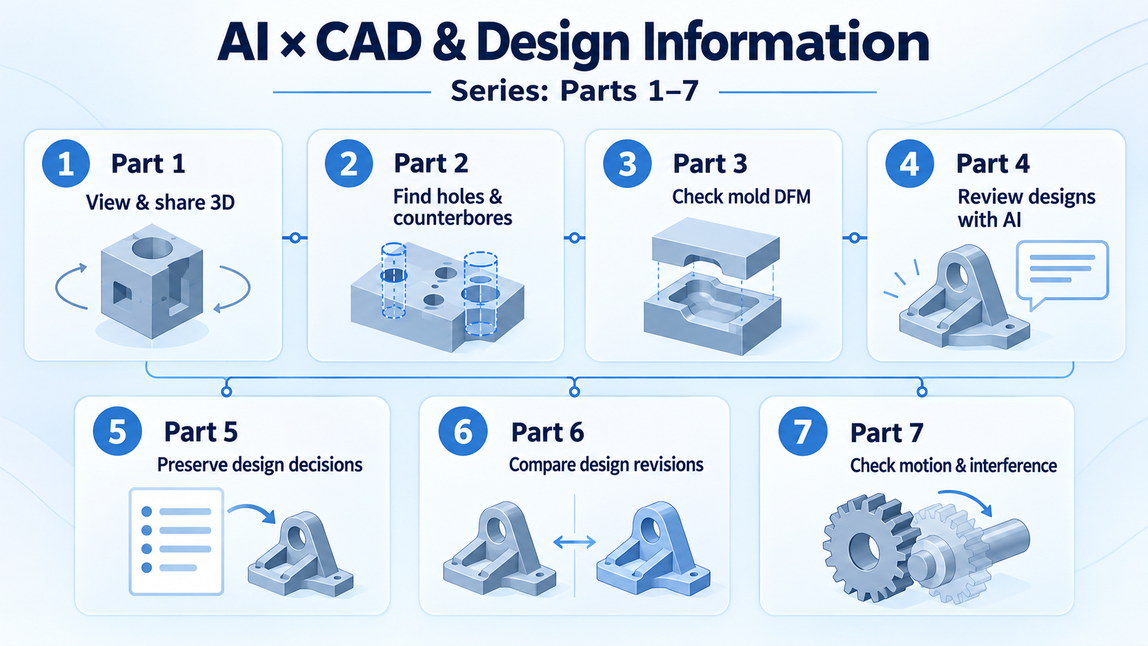
This is Part 2 of our seven-part "AI × CAD & Engineering Data" series!
Every time a quote is due, you open the drawing and count holes.
Four φ6, three φ8 blind holes, counterbores here and here.
You copy the tally into Excel, then phone someone later about the counterbore depth you missed. The 3D data has been sitting right there all along, yet the take-off is still done by eye, even today.
In a STEP file exported with analytic surfaces, the dimensions of the surfaces that make up holes, counterbores, countersinks and fillets are recorded as numbers.
The radius of a cylindrical surface, the apex angle of a conical surface, which way a face points. What people count by eye is exactly what machines can read.
Part 1 covered opening STEP in the browser to view, measure, section and hand over. This time we go one level deeper. Our free 3D CAD viewer and AI analysis tool "CADAS" ships with feature recognition — it automatically picks up holes, counterbores, countersinks and fillets from the STEP B-Rep and lays them out in a table — and this article explains how it works, from the implementer's side. Every number is an actual measurement.
First, try the real thing ↓
The hole-type plate below is embedded with exact analysis already completed.Click a row in the table on the right and the corresponding holes light up in 3D.Drag to rotate, scroll to zoom. Counterbores are colored red, countersinks blue, blind holes yellow.
This embed itself is a CADAS feature. You can paste the analyzed state, results and markings included, into any website or blog as an iframe. How it all works is covered step by step below.
Open the hole-type plate and 12 holes become a 5-row table
The CADAS Sample Gallery includes a model called the hole-type plate: a 100×70×12 mm plate carrying through holes, blind holes, counterbores, countersinks and a blind hole on a boss. We generated it ourselves with cadquery, so the correct dimensions are known.
Load it and a "Hole Table" tab appears in the right pane. On my machine (Windows + Chrome), the table showed up 2.8 seconds after pressing the confirm button in the gallery.
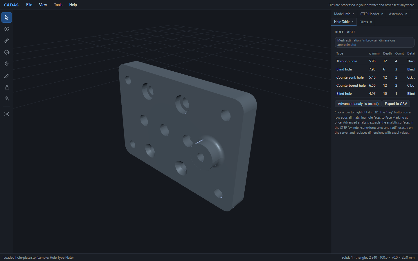
Four through holes, three blind holes, two countersinks, two counterbores, one blind hole on the boss. Types and counts match the design, but look closely at the diameter column: φ5.96, φ7.95, φ6.56 — each slightly off. The design values are φ6, φ8 and φ6.6.
There is a reason for this drift.
In-browser analysis "estimates circles from triangles"
Right after loading, what CADAS holds in the browser is the triangle mesh parsed from the STEP file, plus a map of which B-Rep face each triangle belongs to. To find holes from this, it examines the distribution of triangle normals per face, statistically decides "this looks like a cylinder" or "this looks like a cone", then fits a circle to estimate the radius.
Triangle vertices sit on the circle, but triangle centroids fall slightly inside it. That is why a φ6 hole comes out as φ5.96 — an approximation this centroid-based method cannot avoid. It is enough for classifying types and counting, but
as a number you put on a quote, you want one step better.
So CADAS uses a two-stage approach.
Press "Advanced analysis (exact)" under the hole table and a confirmation dialog appears.
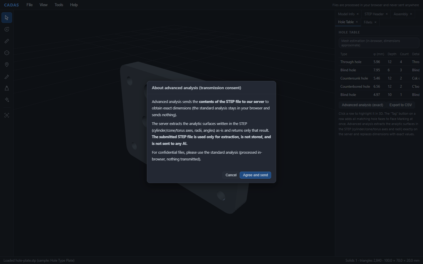
Consent and send, and the server reads the analytic-surface entities directly from the STEP body and returns only the results. The round trip took 0.82 seconds for the hole-type plate (109 KB), and the same 0.82 seconds for the 1.03 MB reduction gear unit.
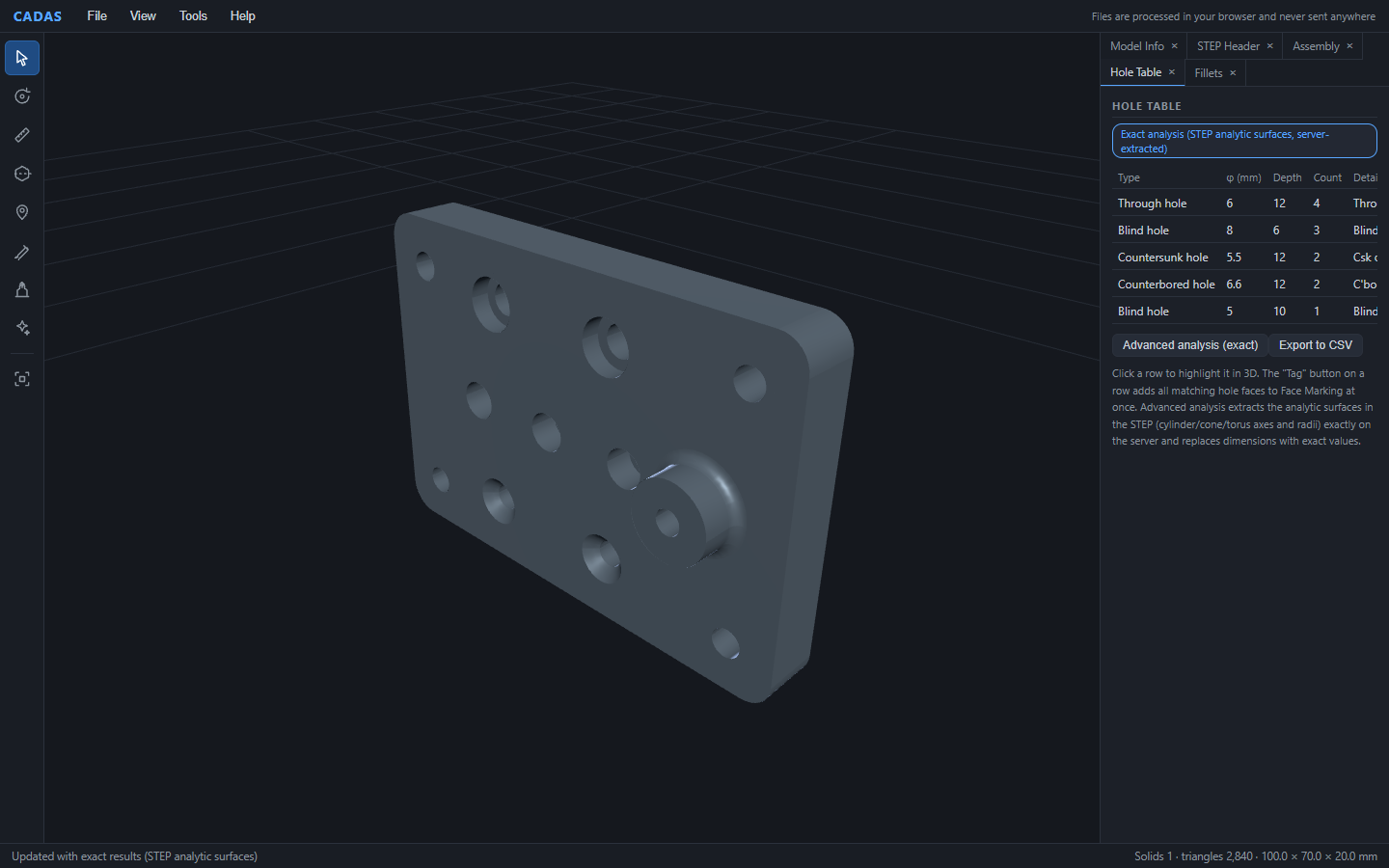
φ6.000, φ8.000, a 90° countersink at φ10.400, a counterbore φ11.000 at depth 4.000. They match the design values to the third decimal place. Mesh estimation and exact analysis side by side look like this.
| Hole | Design value | Mesh estimate | Exact analysis |
|---|---|---|---|
| Through hole ×4 | φ6.0 through | φ5.96 | φ6.000 |
| Blind hole ×3 | φ8.0 depth 6 | φ7.95 depth 6 | φ8.000 depth 6.000 |
| Counterbore ×2 | pilot φ6.6 / bore φ11 depth 4 | φ6.56 / φ10.95 depth 4 | φ6.600 / φ11.000 depth 4.000 |
| Countersink ×2 | pilot φ5.5 / cone φ10.4 90° | φ5.46 / φ10.33 90° | φ5.500 / φ10.400 90.0° |
| Blind hole on boss ×1 | φ5.0 depth 10 | φ4.97 depth 10 | φ5.000 depth 10.000 |
Both paths get every type and count right, and exact analysis delivers the very dimensions recorded in STEP (matching the design values for this sample). This division of labor is the backbone of feature recognition in CADAS. You can count confidential files with in-browser estimation alone, and decide for yourself whether to send to the server when dimensional accuracy matters.
What the STEP B-Rep actually contains
From here on, the internals.
In STEP (ISO 10303) AP203/AP214/AP242, solid geometry can be represented as B-Rep (boundary representation), and this is the representation widely used in ordinary mechanical-CAD STEP exchange. A solid is a closed set of faces, and each face is defined by "which surface it lies on" and "which edges bound it". The surface part is the crux: when exported as analytic surfaces, a cylinder's CYLINDRICAL_SURFACE carries its axis position, direction and radius, a cone's CONICAL_SURFACE carries its half-apex angle, and a torus's TOROIDAL_SURFACE carries its major and minor radii — all written as plain numbers.
Counting the surfaces in the hole-type plate's STEP gives 19 cylindrical, 2 conical, 1 toroidal and 13 planar — 35 faces in total. The 19 cylinders break down as 4 through holes, 3 blind holes, 4 for the counterbores' pilots and bores, 2 countersink pilots, 1 boss blind hole, 1 boss outer wall and 4 corner R6s; the 2 countersink cones are the conical surfaces; the R2 at the boss root is the torus.
What the exact-analysis server does is split the STEP body into records and follow the references —
solid → shell → face → surface
— to pull these numbers out.
Which way a face points comes from the ADVANCED_FACE same_sense flag (whether the face orientation matches or opposes the surface normal) combined with the direction of the surface normal. This is really the same face-orientation math you do with polygons in everyday 3D graphics. And with it, a hole's inner wall and a boss's outer wall can be told apart. Project the boundary vertices onto the axis and you also get the height range the cylinder spans — in other words, the hole's depth.
Assembling the extracted surfaces into holes is the classifier's job. The rules are as follows.
| Configuration of coaxial inward-facing surfaces | Classification |
|---|---|
| One cylinder diameter, no cap at either end | Through hole |
| One cylinder diameter, capped at one end | Blind hole |
| Two cylinder diameters, the larger reaching the open end | Counterbore (larger = bore, smaller = pilot) |
| A cone with a 15–75° apex angle at the open end | Countersink (the cone is the seat) |
| Other multi-diameter cases | Stepped hole |
"Coaxial" means the axes are within 0.3 mm of each other; "same diameter" means within 0.06 mm. The classifier is one and the same for mesh-estimated surfaces and exact-analysis surfaces.
The time our through-hole judgment failed
The first implementation decided "through or not" by whether the hole's height range roughly covered the local plate thickness, with the thickness estimated from the height spread of vertices around the hole.
Blind holes broke it. With few vertices around a hole, the thickness came out too small, and a depth-6 blind hole was judged to "roughly cover the plate thickness" — that is, through. Methods that depend on tessellation density betray you in exactly this way.
Now we extend the axis slightly beyond both ends of the hole and directly check whether triangles (the hole's cap) exist there. A cap means blind; none at either end means through. After switching to this judgment, which is far less sensitive to tessellation density, all three samples — the hole-type plate, the reduction gear unit and the 24-part clock movement — came out perfect.
Two more issues were squashed at this stage: planes misclassified as huge torus surfaces, and cones with flipped axes swapping the countersink's large and small ends. In feature recognition, writing the rules takes far less time than watching how they miss on models whose right answers you know.
Click a row and the holes light up
Numbers alone do not tell you which hole is which.
Click a row and every hole of that type is highlighted in the 3D view.
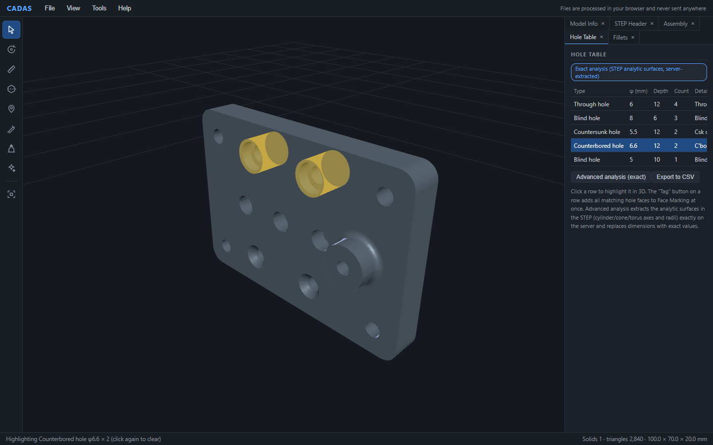
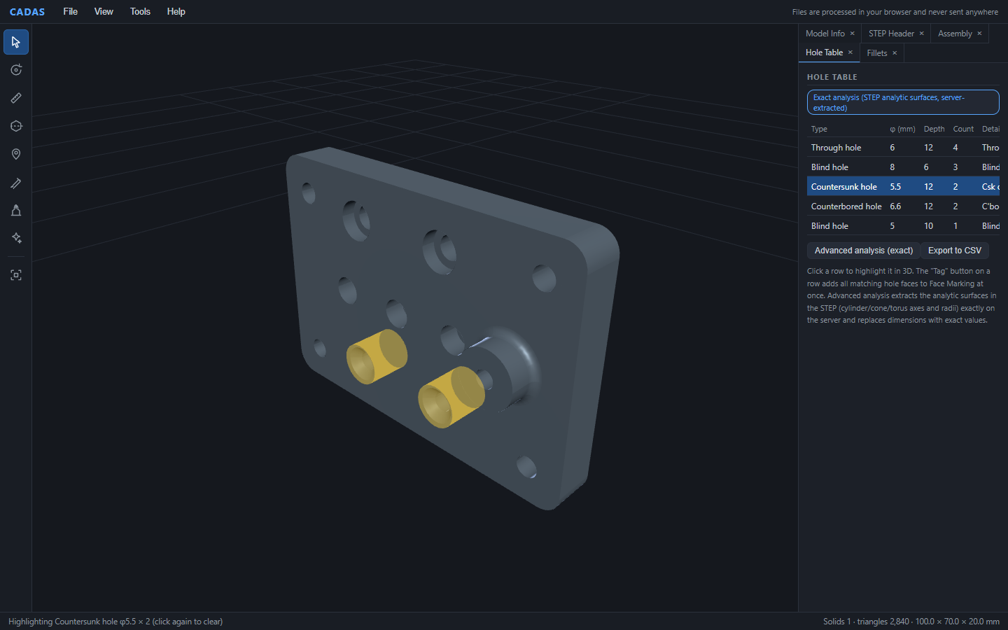
After exact analysis there is no face map, so we place translucent markers along the axis from each hole's position and diameter. Holes behind walls stay visible, so a hole that enters from the back of the plate never gets lost.
Fillets are picked up by the same mechanism
The "Fillets" tab lists torus bands and partial-cylinder bands grouped by R value. On the hole-type plate: one R2 at the boss root (a torus band, a concave fillet) and four R6s at the plate corners (cylinder bands, convex rounds). Exact analysis gives R2.000 and R6.000 here as well.
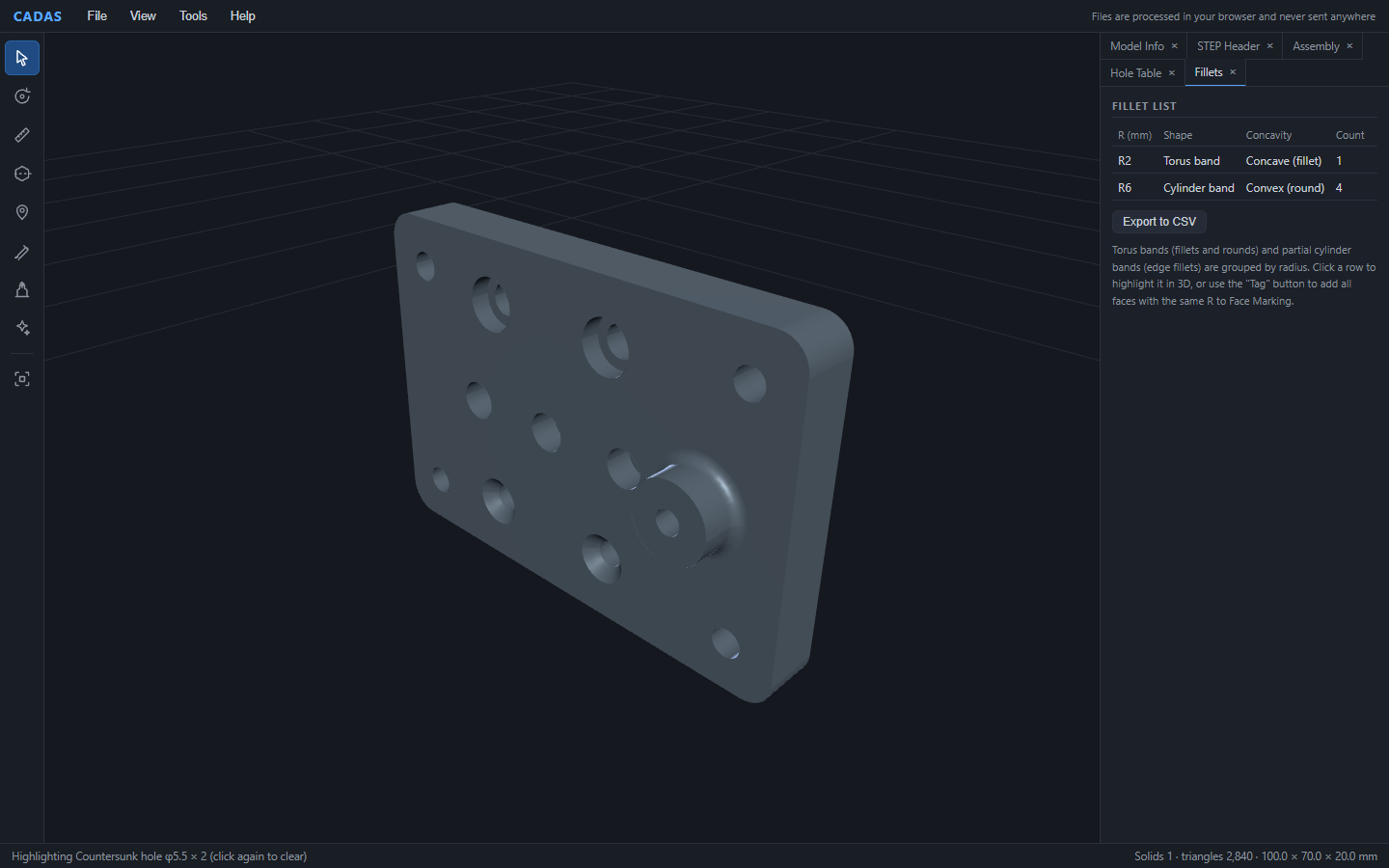
If the smallest R drops below 1 mm, a warning appears above the list — a way to flag too-small radii up front, as a proxy for tool diameter and stress concentration.
Assemblies: counting across parts
A single plate is not enough for real work. Let's try the reduction gear unit (5 parts).
Exact analysis finds four counterbores φ5.5 (bore φ9 × depth 3), two φ10 through holes and two φ10.2 through holes. The φ10s are the bores of the two gears; the φ10.2s are the shaft holes in the base plate — different parts. Per-part dimensions gather into a single table.
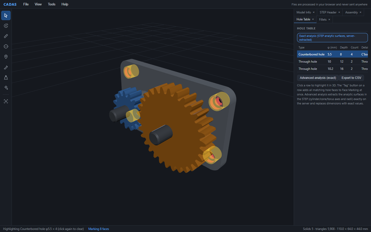
Here is the real thing again, embedded below. Click the "Counterbore" row — the four corners of the base plate light up.
In an assembly STEP, each part is defined in its own local coordinates, with placements and transforms expressed by separate groups of entities. Exact analysis composes these transforms recursively from the parent down, converting hole positions into world coordinates. A regression test pins the corner counterbores at (±45, ±22), so the highlights do not drift when parts move.
What to do with the table once you have counted
The hole table exports as-is via "Export to CSV". Here is the actual output for the hole-type plate.
"Type","φ (mm)","Depth (mm)","Count","Detail","Part"
"Through hole","6","12","4","through","hole-plate"
"Blind hole","8","6","3","blind","hole-plate"
"Countersink","5.5","12","2","cone φ10.4, 90°","hole-plate"
"Counterbore","6.6","12","2","bore φ11 × depth 4","hole-plate"
"Blind hole","5","10","1","blind","hole-plate"
For a quote take-off, you just match these five rows against your price list.
No transcription, no recounting.
One more thing: press the "Tag" button at the right end of a row and every face of that hole type is registered to face marking in one go. Tagging the counterbore row on the reduction gear unit put 8 faces (4 locations × 2 faces), 6.83 cm² in total, under the "Check" tag.
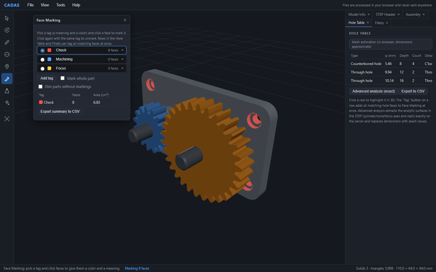
Turn this state into the shared package (.cadas) introduced in Part 1 and hand it over, and the recipient opens the model with the hole table and markings already in place. You get to ask "are all these counterbores the same depth?" while both of you look at a 3D model with the holes colored in.
Instead of handing over a file, you can also embed the analyzed state straight into a web page. The embeds at the top of this article and in the reduction-gear section are exactly that — iframe tags issued from "File > Get Embed & Share Link", pasted as-is. Put one on your intranet portal and departments without CAD can spin the 3D model while reading the hole table. To restrict viewers, you can set a username and password when issuing the link.
Validated against models with known answers
Feature recognition cannot be trusted just because a plausible-looking table shows up.
Here is how we validate it.
We restricted the test subjects to models we generate ourselves.
Both the hole-type plate and the reduction gear unit are built from cadquery scripts, so the design values — such as the φ6.6 counterbores sitting at (−20, 22) and (10, 22) — are written in the scripts. Regression tests check against these values: approximate tolerance for mesh estimates, agreement within 0.001 mm for exact analysis.
On top of that, we verified that the tests actually catch defects. We deliberately injected three — disabling the cap check in through-hole judgment, removing the cone end-radius swap, stopping assembly transform composition — and confirmed the tests fail on each before adopting them.
A test that fails when it should is worth more than a test that passes.
Wrap-up
In STEP files exported with analytic surfaces, the dimensions of the surfaces that make up holes, counterbores, countersinks and fillets are recorded as numbers. CADAS counts them with in-browser mesh estimation, and only when needed replaces them, through exact server-side analysis, with the precise geometric values recorded in the STEP's analytic surfaces.
On our self-generated samples, those values matched the design values to the third decimal place. The 12 holes of the hole-type plate become a 5-row table, drop into CSV, get their faces colored, and travel in a shared package.
A take-off that used to be counted by eye becomes load-and-click.
The next installment, Part 3, is about molds.
"This part won't release from the mold"
— we run the automatic draft, undercut and wall-thickness checks that catch this during design, on a plastic case with known answers.
Start by opening the hole-type plate
CADAS is free, with no sign-up. Choose the hole-type plate from "File > Sample Gallery" and open the "Hole Table" tab in the right pane. If you load your own STEP file, it counts with in-browser estimation as-is.
Open CADAS in your browser (free, no sign-up)
Our consulting division supports innovation in engineering workplaces with AI and IT — from source code to 3D CAD data — end to end, from problem discovery through solution deployment. If you are interested, feel free to reach out via AI × CAD & Engineering Data consulting (free initial consultation).
See you in the next article!
Related links
CADAS - 3D CAD viewer and AI analysis tool (free, developed by Qualiteg)
AI × CAD & Engineering Data Consulting | Qualiteg (about our consulting)