
[AI×CAD] Part 3: Catch "This Shape Won't Release" While You Design — Automatic Mold DFM Checks (Draft Angles, Undercuts, Wall Thickness) in a Browser
Draft angles, undercuts and local wall thickness can be pre-checked from geometry once you pick the mold-opening direction. We ran CADAS's mold DFM on a plastic case with deliberate defects and explain how it reaches 11.8% needs-draft, 0.2% undercut (side hole only) and a 2.00 mm median thickness.

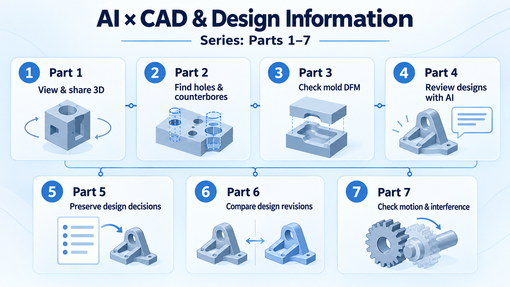
![[AI×CAD] Part 3: Catch "This Shape Won't Release" While You Design — Automatic Mold DFM Checks (Draft Angles, Undercuts, Wall Thickness) in a Browser](/content/images/size/w1200/2026/09/ai-cad-step-viewer-part3-en.png)
Hello!
After handing 3D data to a mold maker, have you ever had messages like these come back?
"This side hole won't release with a Z-direction pull."
"This rib has no draft."
"This area is too thick and will sink."
The points are valid. The trouble is that they come back only after the design is essentially done and the drawings have gone out. The fix is on our side, and once fixed, another round of checking begins.
Draft angles, undercuts, and local wall thickness can be given a first-pass check from the geometry once the mold-opening direction is decided. If you find the candidates while still designing, the meeting with the mold maker moves from "where is the problem" to "how do we fix this spot." Decisions that depend on material and molding conditions are then made with those candidates and the 3D shape in hand.
This article is Part 3 of the "AI × CAD and Design Information" series. Our free 3D CAD viewer and AI analysis tool "CADAS" now carries a mold DFM function (draft angle, undercut, wall thickness, and rib/boss detection). We ran it on a plastic case whose correct answers are known, and describe how it works from the side that implemented it. Every number here is a measured value.
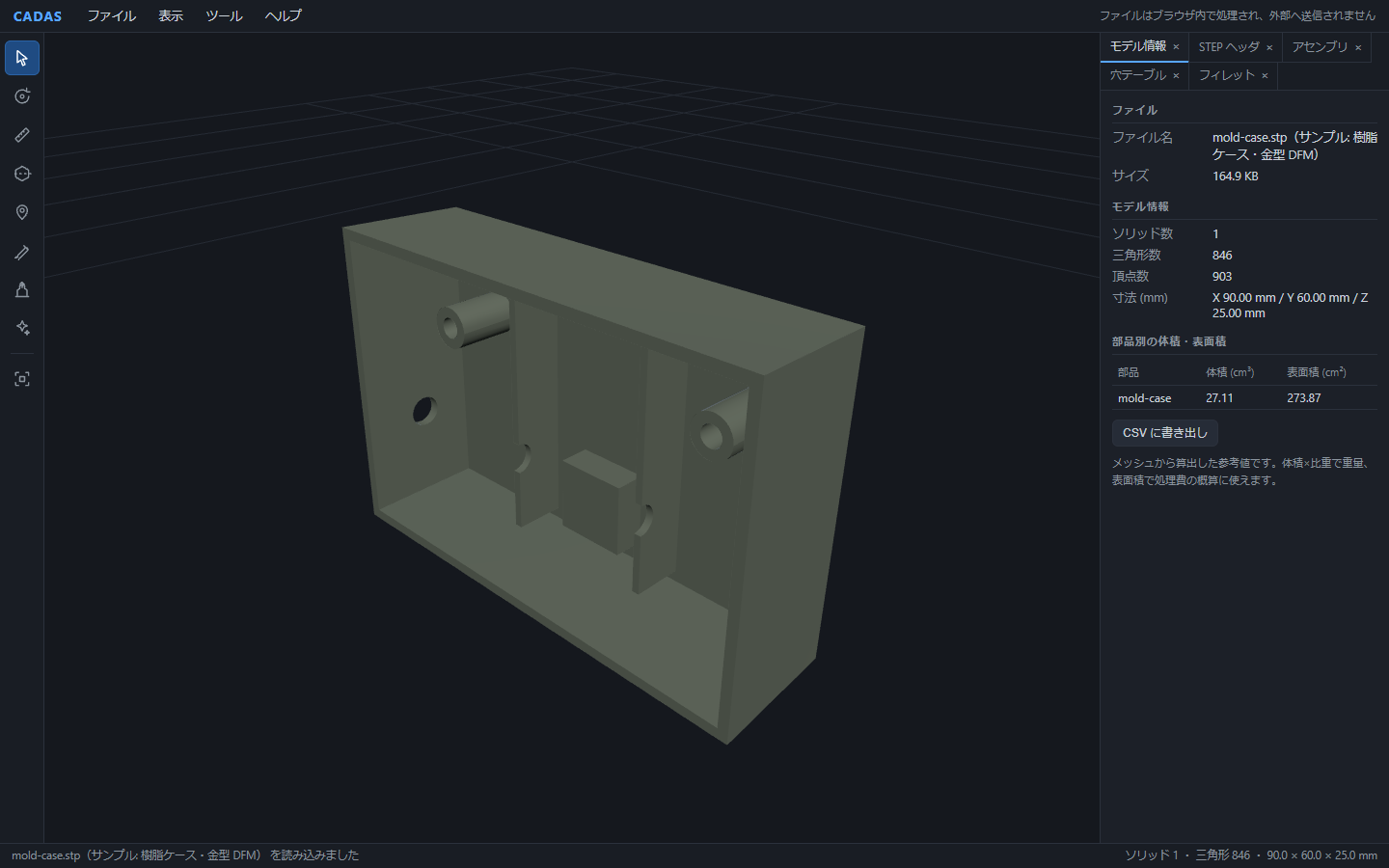
Testing on a plastic case with draft-free ribs and a side hole
For verification you need a model whose answers are known. The "plastic case" in the CADAS sample gallery is a mold-part-style model we generated with cadquery, with the following elements built in on purpose.
| Element | Design value | Expected DFM result |
|---|---|---|
| Outer shape | 90×60×25 mm, open top, 2° draft on walls | Releases with a Z pull (OK) |
| Shell thickness | 2.0 mm | Median thickness 2.0 |
| Inner ribs ×2 | 1.5 mm thick, height 10, no draft | Needs draft (vertical faces), detected as thin walls |
| Bosses ×2 | Outer diameter φ8, height 12, no draft | Needs draft, detected as bosses |
| Side hole in the wall | φ6, axis along X | Does not release with a Z pull (undercut) |
| Thick pad on the inner floor | 14×14×6 (8 mm together with the 2 mm floor) | Thick side of the thickness map |
It is a small model of 846 triangles. Loading took 2.4 seconds on the author's machine (Windows and Chrome).
Pick the mold-opening direction and press "Analyze draft"
Selecting the mold DFM tool (D key) from the tool palette on the left opens a floating window. Set the mold-opening direction (Z by default) and the draft threshold (0.5 to 5°), then press "Analyze draft." That is all.
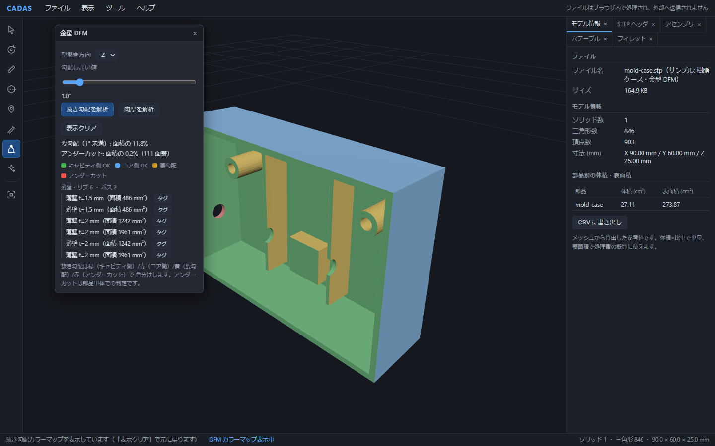
Here is what came out.
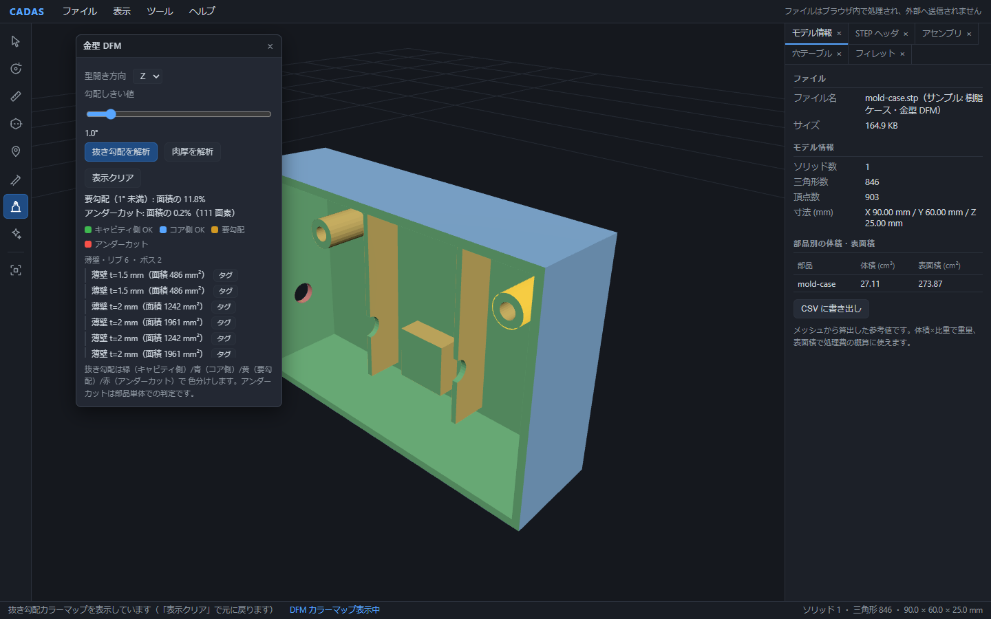
Needs-draft (under 1°) covers 11.8% of the area. The yellow faces are the vertical faces of the two ribs and two bosses, exactly the places where the design has no draft. The outer and inner walls with 2° draft split cleanly into the cavity side (green) and the core side (blue).
Undercut covers 0.2% of the area, 111 facets. The only red faces are the inner wall of the side hole. Rotate the model to look at the +X wall and the rim of the hole shows up as a red ring.
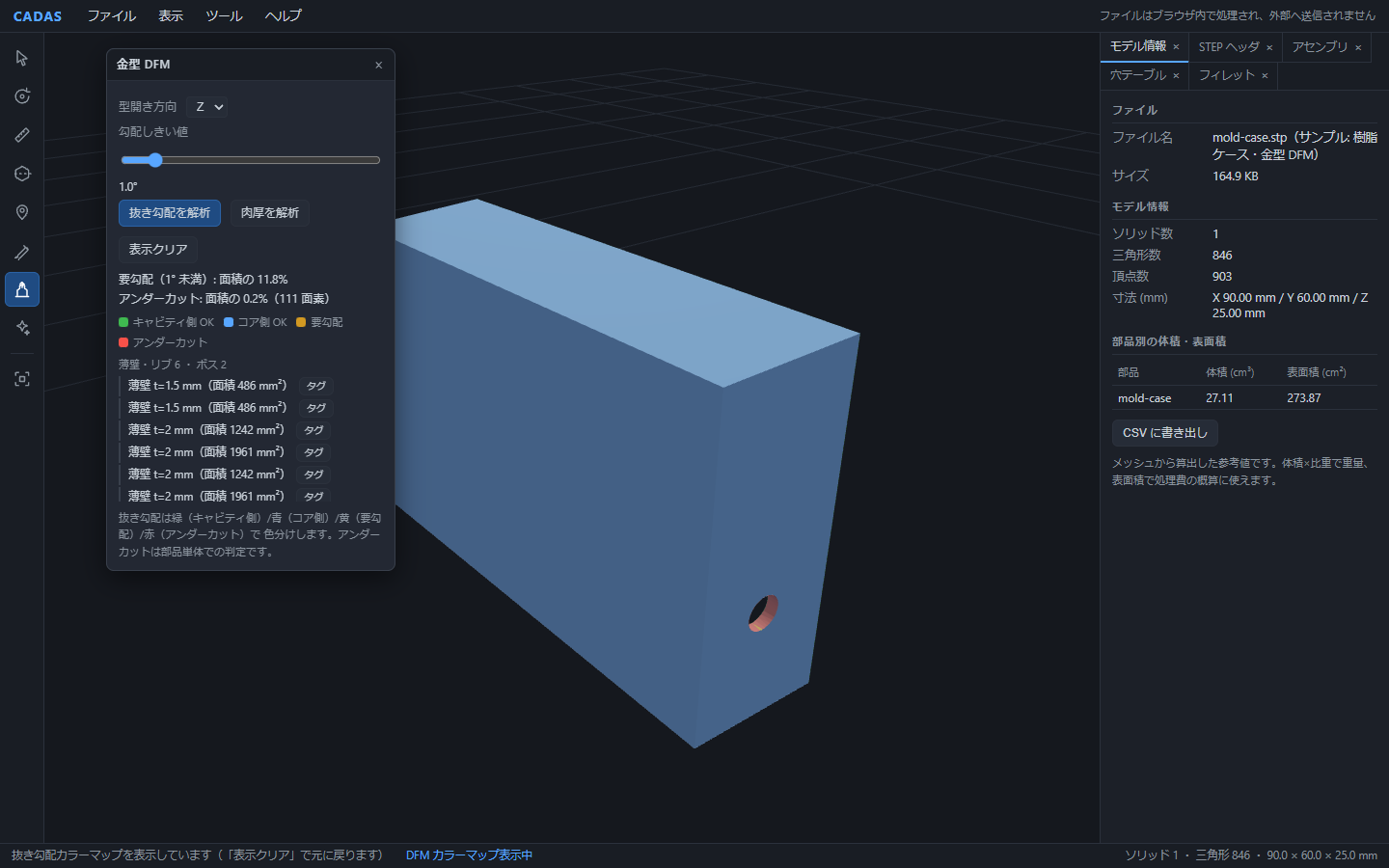

At this point, two of the three comments that come back from mold makers (no draft, won't release) have become colors with a single button press.
Inside the judgment: face orientation and ray occlusion
Classifying draft is simple. For each triangle, the dot product of its normal n and the mold-opening direction d gives the sine of the draft angle. With θ = asin(n·d), a face releases on the cavity side if θ exceeds the threshold, on the core side if −θ exceeds the threshold, and is a near-vertical "needs draft" face if the absolute value is below the threshold.
Undercuts cannot be found that way alone. A face may point in a releasing direction and still be trapped if another part of the same body sits above it. So for every triangle other than the needs-draft ones, we cast a ray from its centroid in its releasing direction and check whether it hits another triangle of the same part. If it does, the face is red.
Because every ray is parallel to ±d, projecting the triangles onto a plane perpendicular to d and binning them in a 2D grid (48×48) limits each ray's candidates to the triangles in the same cell. Draft analysis on the plastic case took 15 ms, measured with node on our development machine.
Incidentally, running the same analysis with the opening direction changed to X or Y sends the undercut figure up to 19.7% and 18.5%. That is expected, since pulling an open-top box in any direction other than Z traps most of the inner walls. Seen the other way, it also gives you material for comparing which direction is promising.
Set the threshold to 3° and the 2° walls turn yellow
How many degrees of draft are enough depends on the material, the surface finish, and the release conditions. That is why the threshold is a slider.
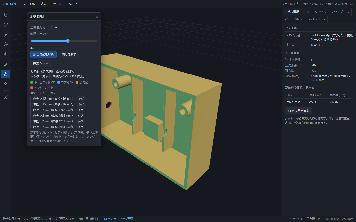
Needs-draft was 11.8% at a 1° threshold, 34.3% at 2°, and 62.1% at 3°. The design used 2° of draft, so the moment the threshold passes it, the whole wall flips to yellow. This behavior is part of the regression tests, pinned as a relative condition: "at 3°, at least twice the needs-draft area of 1°."
If the mold maker says "with our material we want 3°," you move the slider to 3° and look at the same screen. That is how the tool is meant to be used.
Wall thickness is measured as the distance to the opposite face
Press "Analyze thickness" and the coloring switches to a thickness map.
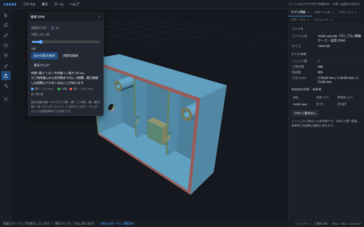
From each triangle's centroid we cast a ray opposite to the normal (into the part) and take the distance to the first face hit as the local thickness. On the plastic case the median is 2.00 mm, which is exactly the designed shell thickness. The top of the thick pad reads around 8 mm together with the 2 mm floor, and 296 facets exceeded 7 mm.
The maximum shows 50 mm because a ray cast downward from the rim of the top opening passes through the opening and reaches the inner floor; the window notes this too. When hunting for thick spots, ignore these across-the-opening values.
For the ray casts we build a uniform 3D grid (24³) and walk the cells with a grid traversal (DDA, the Amanatides-Woo method). It takes 11 ms for 846 triangles, and up to 20,000 triangles are measured in full without sampling.
Ribs and bosses: jump from the list to 3D
Below the draft results there was a list reading "thin walls/ribs 6, bosses 2." Thin walls are pairs of anti-parallel planes 0.3 to 6 mm apart (a list of candidates whose thickness you may want to check, not a count of defects); bosses are outward-facing cylinders standing along the mold-opening direction.
On the plastic case, besides the two t=1.5 mm ribs (as designed), it listed four t=2 mm shell walls, and two bosses of φ7.95 × height 12. The boss diameter comes out 0.05 mm under the designed φ8 because it is estimated from the mesh (the estimation method was described in Part 2).
Give the detected spots a color and a meaning, then hand them to the mold maker
This is where it pays off most in practice.
Each row in the list has a "Tag" button; pressing it registers that element's faces in face marking. Tagging the two ribs put 4 faces, 19.44 cm², into the "Needs review" tag.
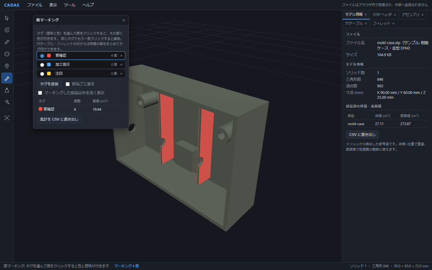
The totals can be exported to CSV. Here is the actual file.
"Tag","Color","Faces","Total area (mm2)","Total area (cm2)"
"Needs review","#f85149","4","1944","19.44"
"Machining note","#58a6ff","0","0","0"
"Attention","#ffd23e","0","0","0"
These markings, sticky notes, and viewpoints can be bundled into a share package (.cadas) and handed to the mold maker. When they drag and drop it into CADAS, they open the 3D with the ribs to be reviewed marked, plus the comments placed at those spots. Write the analysis conditions on a note too, "opening Z, draft threshold 1°," and the assumptions behind the review travel with it.
You can then discuss while pointing at the shape: "how many degrees of draft does this rib need," or "keep the side hole and use a slide, or change the hole's direction." The other side can rotate the model and look at the back themselves. Tying each comment to its location cuts the back-and-forth of figuring out which spot an email's "this side" or "the rear rib" refers to.
Discuss the same shape, then check again after the fix
If the model may be published, there is another route: choose "Share the current view state" under "File > Embed / share link" and hand over a URL that includes the notes and markings. The recipient just opens the link and sees the spot in 3D. URL sharing uploads the model, so for parts that cannot leave the company, create the .cadas file on your own machine and pass it through a channel approved internally.
Once the rib draft has been revised after the meeting, analyze the revised STEP with the same opening direction and the same threshold. Do not stop at "less yellow"; look at the revised rib faces and confirm they now have the agreed draft. Being able to run this loop during design is the value of DFM in a browser.
CADAS has also gained a feature that overlays the STEP before and after a change and shows per-part differences, useful for pointing out what was modified. The concrete steps for comparison will be covered in Part 6; this part stays focused on aligning the mold-opening direction and the molding checks.
The analysis caught a design mistake the moment the sample was made
A confession: the first version of this plastic case would not have released.
The loft I wrote to give the open-top box a 2° draft ran the wrong way, producing a box that narrows toward the top. Running draft analysis on it gave 23% undercut by area, with the inner walls entirely red. Only the side hole should have shown, so I re-examined the model and noticed the loft direction.
After the fix, undercut dropped to 0.2%, with only the side hole red. The tool found a design mistake in the very model built to verify it, and that was the moment the value of running DFM mid-design really landed.
Verified against ground truth, with injected defects
Part 2 set the approach, and we follow it here. The regression tests require, based on the design values, that the centroid mean of the undercut triangles lies at the side hole (y≈−10, z≈12), that needs-draft at a 3° threshold is at least twice that at 1°, that the median thickness is 2.0±0.2, and that two t=1.5 ribs and two φ8 bosses are detected.
On top of that, we deliberately introduced three defects, disabling the occlusion test, stopping the grid traversal (DDA), and breaking the rib thickness condition, and confirmed that the tests fail on each before adopting them.
Summary
Draft is estimated from the angle between the normal and the mold-opening direction, undercut from ray occlusion in the releasing direction, and wall thickness from the distance to the opposite face along the normal. All of it is deterministic geometry on the mesh, not an LLM, and the plastic case turns into colors in 15 ms. The threshold is a slider you set to match the material, and the detected spots can be tagged and handed over in a share package.
You can surface the candidates for "this shape won't release" yourself, in the middle of design.
Part 4, next time, is about AI.
It covers how we built CADAS's AI findings, which let AI review a design without handing over the 3D data.
Start by coloring the plastic case yourself
CADAS is free and needs no registration. Pick the plastic case from "File > Sample gallery," press the mold DFM tool (D key) in the left palette, and "Analyze draft." With a STEP of your own plastic part, the same colors appear once you choose the opening direction. The analysis runs entirely in the browser; files are never sent anywhere.
Open CADAS in your browser (free, no registration)
For tuning the judgment rules to your own molding conditions, or designing how DFM results are shared between design and the mold maker, AI × CAD and Design Information Consulting (free initial consultation) is available. Feel free to get in touch.
See you next time!
Related links
CADAS - 3D CAD viewer and AI analysis tool (free, developed by Qualiteg)
AI × CAD and Design Information Consulting | Qualiteg (consulting overview)