
[AI×CAD] Part 5: Preserve the "Why" That CAD Alone Cannot Explain — A Practical Approach to Design Knowledge and Local LLMs
CAD records the final geometry, but geometry alone cannot explain why. Ask designers questions grounded in geometric facts, preserve their reasons alongside the model, and use revision comparisons to put design knowledge and local LLMs in a practical workflow.

![[AI×CAD] Part 5: Preserve the "Why" That CAD Alone Cannot Explain — A Practical Approach to Design Knowledge and Local LLMs](/content/images/size/w1200/2026/09/ai-cad-step-viewer-part5-en.png)
Hello! This is the Qualiteg Product Development Team!
In our consulting work, we are increasingly asked about using CAD and other design information, and passing design knowledge to the next generation. The underlying concerns are often similar.
All the historical 3D data and drawings are there. They are searchable. Yet when experienced engineers leave, the same mistakes happen again.
A central issue is the kinds of information being preserved. CAD records what was ultimately designed. Geometry alone does not explain why it was designed that way. And a general request to "share your knowledge" rarely brings out those reasons.
This is Part 5 of our AI × CAD and Design Information series. Parts 2–4 showed how to extract holes, draft angles, tooth counts, and other information from STEP. Here, we use that information as a starting point for preserving design reasons and discuss local LLMs for information that cannot leave the company.
What CAD preserves, and what geometry alone cannot tell you
Start by separating the information that exists from the information that is missing.
| Preserved information (What) | What geometry alone cannot tell you (Why) | |
|---|---|---|
| Holes | Two φ10.2 through holes at (±22.5, 0) | Why φ10.2 rather than φ10? |
| Gears | Module 2; 15 and 30 teeth; center distance 45 | Why this combination of tooth counts? |
| Mold | 2° draft; 1.5 rib thickness; φ6 side hole | Why was a slide chosen to release the side hole? |
| Geometry in general | The final shape is faithfully recorded | Rejected alternatives, conditions, and constraints at the time |
Information in the left column can be extracted from STEP, as demonstrated in Part 2 through Part 4. The right column is not written into the geometry. It may exist only in the designer's memory, old emails, or recollections of a meeting.
The right column is especially vulnerable when design knowledge is handed over.
Attach the reason to the geometry
Many companies have tried design standards or collections of know-how to preserve these reasons. Such documents often fall out of use for similar reasons: prose separated from geometry is hard to find when needed, and readers may not know where it applies to their own design.
A practical way to preserve a reason is to attach it to the geometry where the decision appears.
CADAS notes provide a minimal implementation. Select Notes (N) and attach a comment to the geometry under discussion. Ask the actual designer to record, for example, "Decision: moved the mounting position. Reason: [reason]. Valid when: [conditions]. Recheck if: [change]." Record the designer's explanation in those fields; do not fill the gaps with guesses.
Each note also records the viewpoint at the time it is placed. Clicking it in the list restores that view. Check the part name and location, then reread the decision about that feature. Exporting CSV lets you handle part names, coordinates, and comments as a table.
A share package (.cadas) passes the notes, viewpoints, and markings along with the model. The recipient can verify the subject of the explanation directly in 3D.
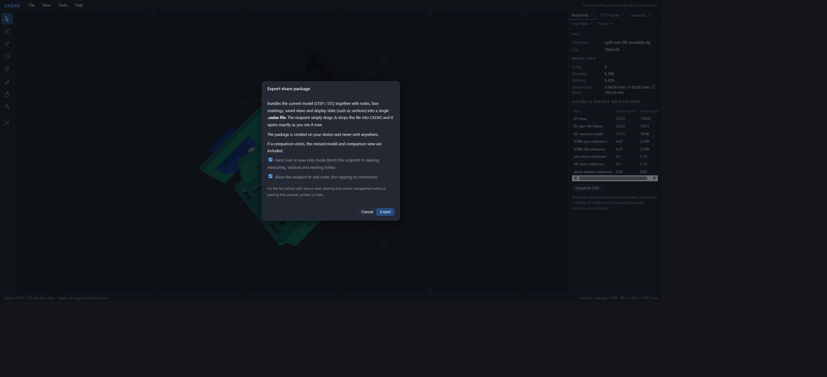
Try adding one question about a sample part, saving it as a share package, and reopening it. Confirm that its note takes you back to the intended subject and viewpoint. Establishing the subject before recording a reason also helps prevent incorrect knowledge from being preserved.
"Please share your expertise" is not enough
A note system preserves nothing unless someone writes in it. This is one of the hardest parts of knowledge transfer. When asked to document their know-how, experienced designers may find it too obvious to articulate, or write general guidance that is difficult to connect to a specific shape.
We consider it useful to have AI ask specific questions grounded in facts, so the experienced designer can answer them.
Part 4 included this observation about the reduction gear unit:
The 0.2mm difference between φ9.94 and φ10.14 may indicate different fit intentions, but tolerance information is not included.
AI produced this observation from approximate mesh-analysis values of φ9.94 and φ10.14, raising a question about their uses. First verify the parts and the hole diameters specified in the original CAD model. Then ask, "Why did you choose this diameter for this hole?" and record the designer's decision and conditions in a note. A diameter difference alone does not establish a past failure or a tolerance intention; preserve the person's explanation.
Grounding questions in geometric facts reduces unsupported questions. If AI includes a hypothesis, make clear which geometric observation prompted it. Store the answer as a set of decision, evidence, conditions, and outcome linked to the feature—a hole, gear, or rib. The Hole Table in Part 2, DFM results in Part 3, and insights in Part 4 can provide many such starting points.
Change "Please tell us what you know" into "Why is this designed this way?" We see that as the entry point for knowledge transfer.
Preserve the earlier geometry so later readers can follow the decision
Even a written reason may be hard for a successor to follow without seeing what changed. Current CADAS can compare revisions and save both models in a share package. Part 6 explains how to find changed parts. For knowledge transfer, the before-and-after geometry provides context for the explanation.
The linear-stage comparison sample, for example, moves a sensor 15mm along X. The movement is a fact that can be checked in the models. Why it moved, why other options were rejected, and when the decision should be reconsidered are questions for the designer. With both kinds of information available, the next person can compare that decision with their own conditions.
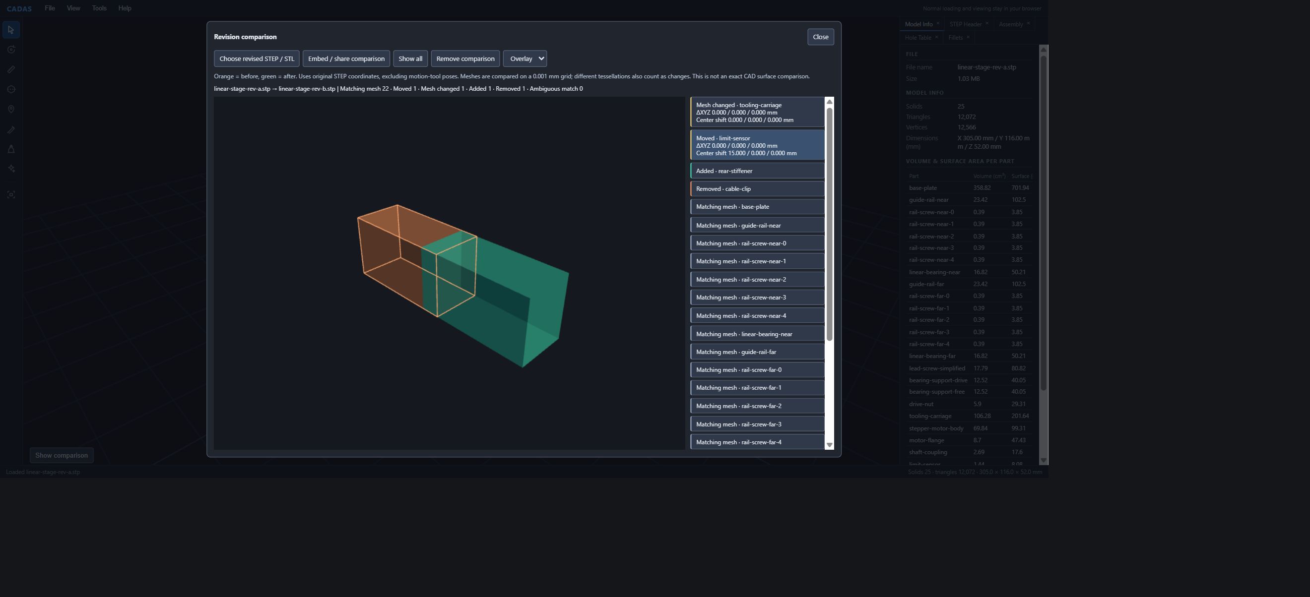
For moving assemblies, the checked pose is useful context too. Open a saved model containing its mechanism definition and angles to show what was checked in which pose. Record the model revision, check conditions, and decision in your own words. Use comparison and saving to establish the records your actual work needs.
Start with one record that another person can follow
There is no need to collect the entire design department's knowledge at once. Choose one hole, rib, or mounting position that you have just decided on, and record the decision, reason, and conditions in a note. Give the .cadas file to another person and check whether they can find the feature, understand the reason, and use it in their next decision.
That one example can reveal missing fields or review steps. Searching accumulated notes and related documents, or answering questions with an internal LLM, can be considered as a subsequent implementation. Design the collection process and search scope around the actual work.
Confidential information can reside in the geometry itself
Trying to run this entire process through cloud-based generative AI can quickly raise a practical issue.
Design confidentiality goes beyond text on drawings. Why this draft angle, this radius, or this gear combination? Those reasons may be precisely what a competitor wants to know. Once a reason is attached to its geometry, the combined record can become highly confidential design knowledge.
If design information is not permitted to reach the cloud, the LLM used for knowledge transfer must also operate within the company. A local LLM becomes an option.
LLM infrastructure is one of our core areas of work, from selecting GPUs and deploying inference engines such as vLLM and Ollama to building internal chat systems. Technical details are available in our LLM Infrastructure Consulting services. Public CADAS currently calls Claude through our server. As Part 4 explained, the LLM call is isolated on the server, and its input is structured data. This separation makes an architecture using an internal local LLM feasible.
"We want to preserve design knowledge with AI, but the data must stay inside" is a design requirement we work with from the start.
Start with the problem and the workflow
Here is the sequence we use when working with clients on this subject. The key principle is to understand the work before selecting tools.
First identify the cause. If the complaint is that mistakes recur after experienced staff leave, use records of rework and defects to establish which decisions in which process steps are involved. Skipping this step risks building another knowledge collection that nobody uses, this time with AI.
Next, check feasibility. Can the relevant decision be approached through a question grounded in geometry? Where does it appear in the CAD data? Use actual client data to check whether the extraction methods shown in Parts 2–4 work for it.
Then run a small proof of concept: one product family, a few experienced designers, and a few dozen reasons. Define the evaluation criteria before starting. Measure whether designs using the records require less rework, or whether new engineers reach the same decision sooner, rather than simply counting captured reasons. Predefined measures make investment decisions more concrete.
This sequence also keeps investment in local LLM infrastructure and internal geometric analysis focused on what is needed.
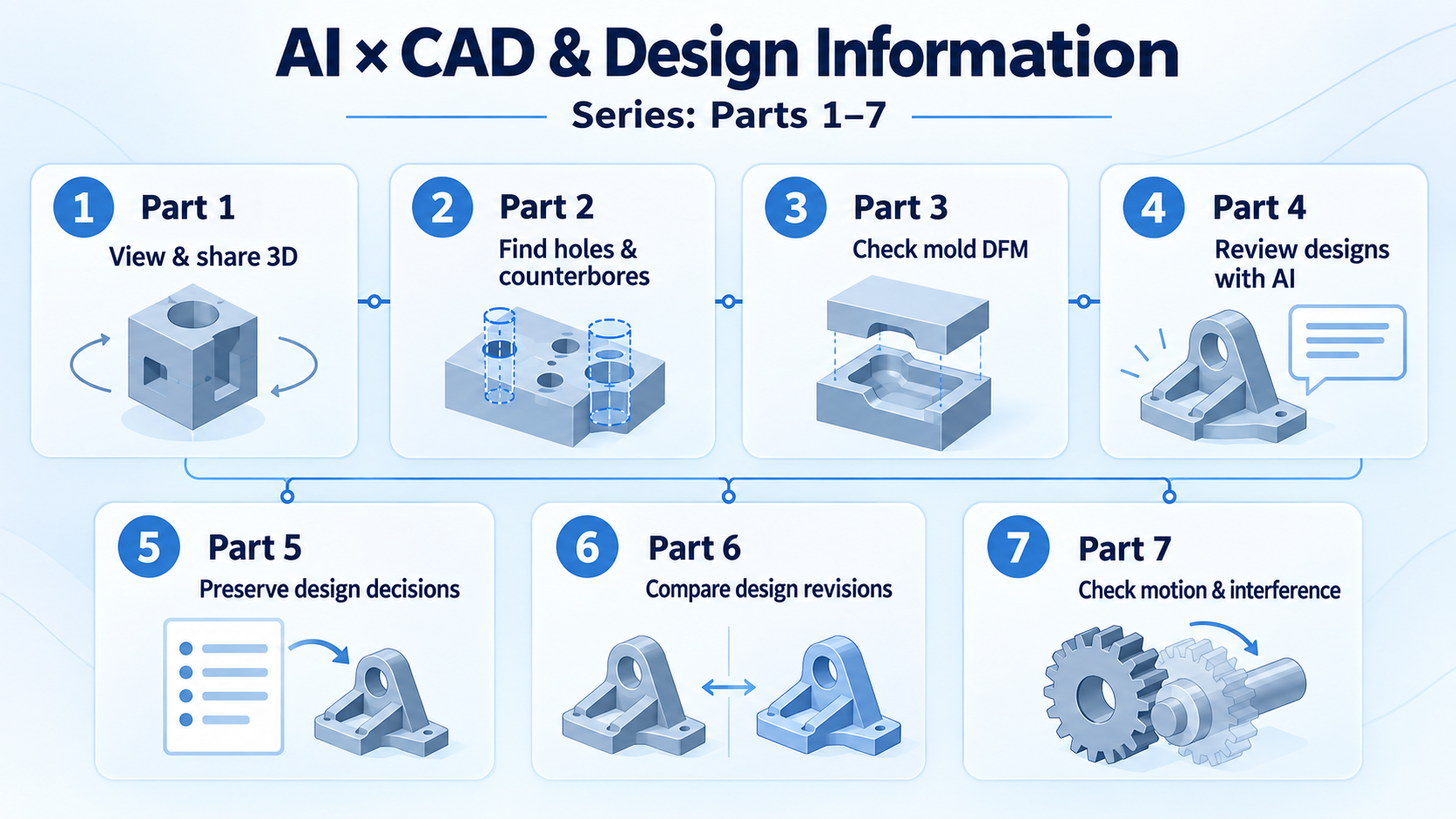
Looking back at Parts 1–5
Here is how the topics covered so far fit together.
| Part | Problem | What CADAS demonstrates |
|---|---|---|
| Part 1 | People outside design cannot view 3D data | Open, measure, section, and share in a browser, with notes and viewpoints |
| Part 2 | Counting holes for every quote | Classify holes, counterbores, countersinks, and fillets; use exact analysis to retrieve geometry recorded as analytic STEP surfaces |
| Part 3 | Release problems are reported after design is complete | Check draft, undercuts, and thickness for a chosen pull direction; tag and share findings |
| Part 4 | Confidential geometry cannot be sent to AI | Analyze geometry first and pass only structured results to the LLM |
| Part 5 (this article) | Reasons are not preserved or passed on | Use facts to ask questions and attach answers to geometry; consider a local LLM for an internal knowledge workflow |
Summary
CAD preserves what was ultimately designed. To retain why it was designed that way, attach the reason to the geometry where the decision appears. Collect it through specific questions based on geometric facts, rather than a broad request to document expertise. This can become highly confidential design knowledge, so keep the LLM internal where cloud transmission is prohibited. Identify the cause, check feasibility, run a small proof of concept with criteria defined in advance, then decide where to invest.
Transferring design knowledge starts with changing the questions you ask.
Talk to us about your workflow
For help managing CAD and other design information or using AI to preserve and transfer design knowledge, see our AI × CAD and Design Information Consulting (free consultation). You do not need a fully defined project. We can start by discussing your existing data and the problems you face.
You can try attaching reasons to geometry in CADAS today. It is free and requires no registration.
Open CADAS in your browser (free, no registration)
Part 6 covers comparing 3D models so people outside the design department can see what changed. It connects the reasons discussed here with the changed geometry. See you in the next article!
Related articles
AI × CAD and Design Information Consulting | Qualiteg
LLM Infrastructure and GPU Environment Consulting | Qualiteg
CADAS — Free 3D CAD Viewer and AI Analysis Tool, Developed by Qualiteg
![[AI×CAD] Part 4: Review a Design with AI Without Sending 3D Geometry to the LLM — Analyze First, Then Pass Structured Results](/content/images/size/w600/2026/09/ai-cad-step-viewer-part4-en.png)

![[AI×CAD] Part 3: Catch "This Shape Won't Release" While You Design — Automatic Mold DFM Checks (Draft Angles, Undercuts, Wall Thickness) in a Browser](/content/images/size/w600/2026/09/ai-cad-step-viewer-part3-en.png)